
Power extension cord with movable outlet modules

a technology of power extension cord and outlet module, which is applied in the direction of flexible lead accommodation, electrical equipment, coupling device connection, etc., can solve the problems of inability to accept other power plugs or plugs of power adapters, inability of conventional retractable power extension cords to accept other plugs or plugs, and complex mechanical structur

Active Publication Date: 2016-04-26
POWERTECH INDAL
View PDF26 Cites 26 Cited by
  • Summary
  • Abstract
  • Description
  • Claims
  • Application Information

AI Technical Summary

Benefits of technology

This design enhances durability, simplifies the structure, reduces manufacturing costs, and allows all outlets to be utilized by increasing the movable space within the cord, effectively addressing the issue of covered receptacles.

Problems solved by technology

However, the power adapters adopted by different electronic product not only do not have unified output standard, the associated volume and shaped may also vary.
Hence, in practice when a user plugs a power adapter into an receptacle of the power extension cord, the power adapter having larger size may cover the nearby receptacle, causing the nearby receptacle unable to accept other power plugs or plug of power adapter.
Nevertheless, conventional retractable power extension cords not only have disadvantages including complex mechanical structure and in the form of larger size, but also having issues of higher manufacturing cost and poor durability.
In addition, as conventional power extension cords are incapable of increasing the gap between adjacent receptacles and the issue of having a receptacle being occupied by a relative large power adapter cannot be effectively addressed by rotating the receptacle at any angle.

Method used


Image

  • Power extension cord with movable outlet modules
  • Power extension cord with movable outlet modules
  • Power extension cord with movable outlet modules

Examples


Embodiment Construction

[0027]Reference will now be made in detail to the exemplary embodiments of the present disclosure, examples of which are illustrated in the accompanying drawings. Wherever possible, the same reference numbers are used in the drawings and the description to refer to the same or like parts.

[0028](An Exemplary Embodiment of a Power Extension Cord)

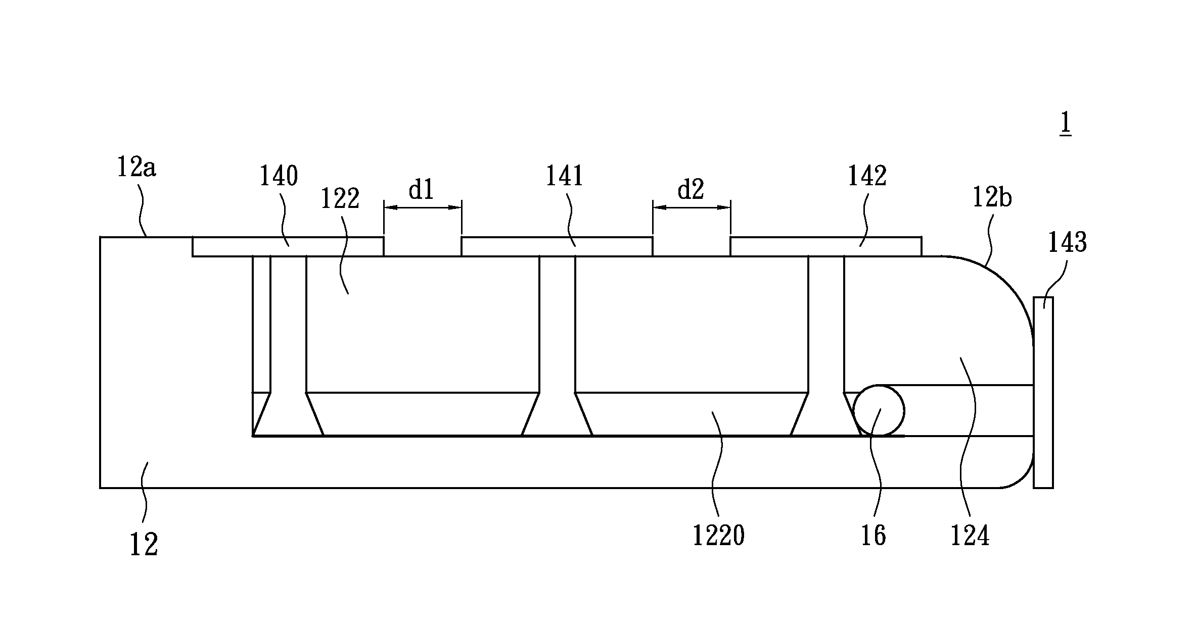
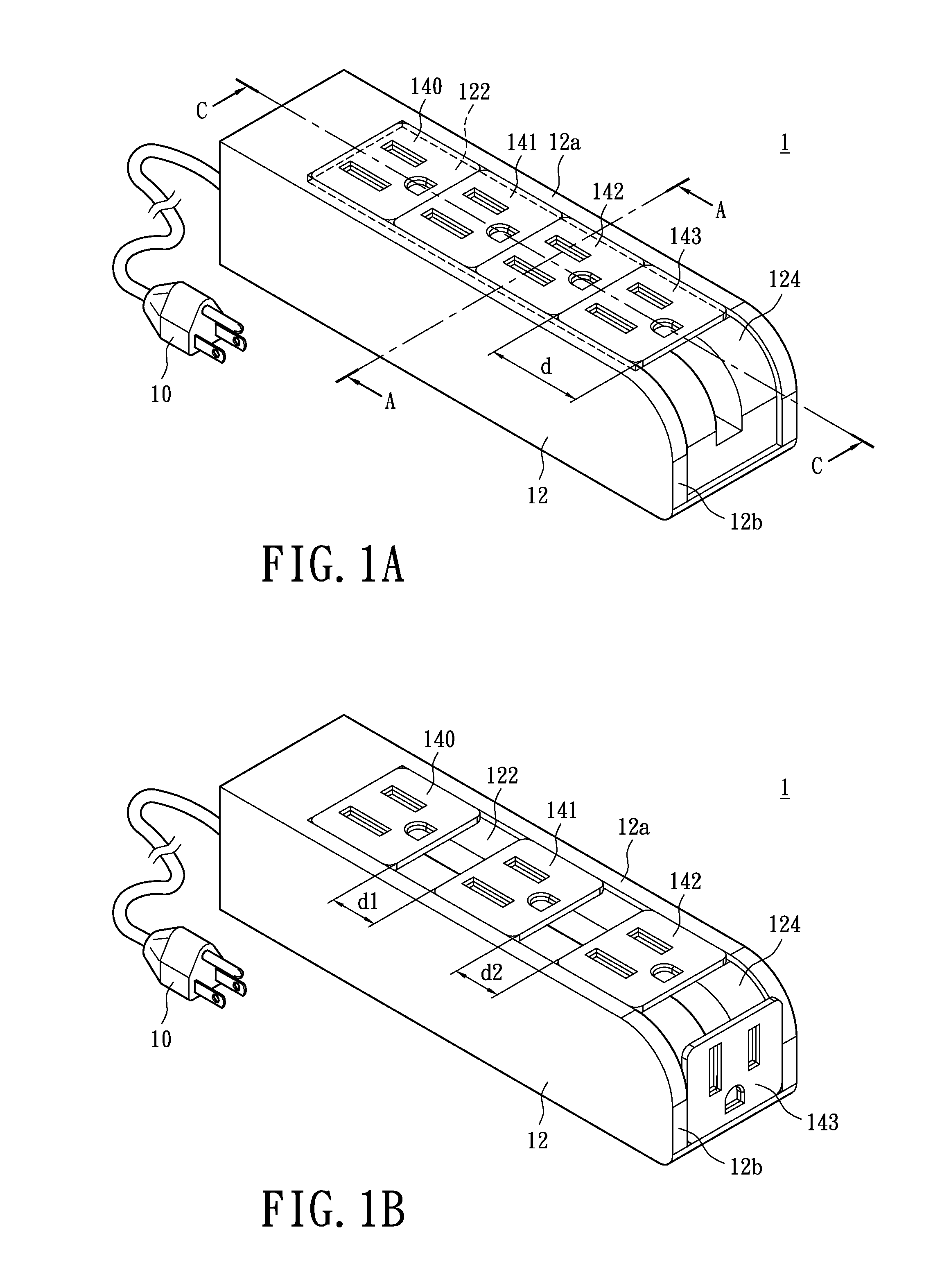
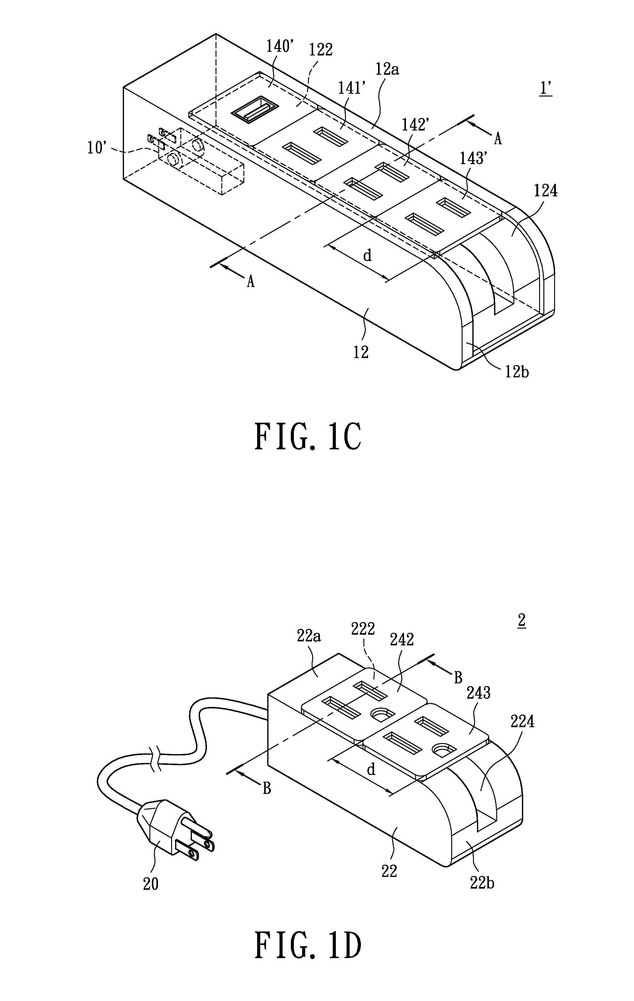
[0029]Please refer to FIG. 1A and FIG. 1B. FIG. 1A shows an isometric diagram illustrating a power extension cord provided in accordance to an exemplary embodiment of the present disclosure. FIG. 1B is an isometric diagram illustrating the power extension cord in operation provided in accordance to the exemplary embodiment of the present disclosure. The power extension cord 1 of the instant embodiment includes a power input portion 10, casing 12, and a plurality of outlet modules 140˜143. The outlet modules 140˜143 are tightly and sequentially arranged on an upper surface 12a of the casing 12. Detail descriptions for each component of power ex...


PUM


Abstract

The present disclosure provides a power extension cord with movable outlet modules, which includes a power input portion, a casing, and a plurality of outlet modules. The power input portion is connected to a city power source. The casing at least includes a first accommodating portion having at least a first sliding track. Each of the outlet modules is electrically connected to the power input portion, and at least one outlet module is movably disposed on the first sliding track. When all the outlet modules are arranged on the first accommodating portion, at least one outlet module becomes immovable on the first sliding track. When one or more outlet modules are dislocated from the first accommodating portion, at least one of the outlet modules becomes movable along the first sliding track. Accordingly, the present disclosure may thus effectively utilize the pin holes associated with each outlet module.

Description

BACKGROUND[0001]1. Technical Field[0002]The present disclosure relates to a power extension cord, in particular, to a power extension cord with movable outlet modules.[0003]2. Description of Related Art[0004]Electronic product generally are equipped with a corresponding power adapter for converting the AC voltage from the city power source to a DC voltage qualifying specific operating requirement to have the electronic product operating normally. However, the power adapters adopted by different electronic product not only do not have unified output standard, the associated volume and shaped may also vary. Hence, in practice when a user plugs a power adapter into an receptacle of the power extension cord, the power adapter having larger size may cover the nearby receptacle, causing the nearby receptacle unable to accept other power plugs or plug of power adapter.[0005]Recently, industries have offering a retractable power extension cord in overcoming the aforementioned issue. However...

Claims


Application Information

Patent Timeline
Patent Type & Authority Patents(United States)
IPC IPC(8): H01R25/00H01R31/06H01R35/04H01R13/72
CPCH01R31/06H01R25/003H01R35/04H01R13/72
Inventor HSU, JUNG-HUI
Owner POWERTECH INDAL
Learn More