Tip-plate assembly, hearing device with a tip-plate assembly and method of manufacturing a hearing device with a tip-plate assembly

a technology of tip-plate assembly and hearing device, which is applied in the field of hearing devices, can solve the problems of limiting the possible insertion depth of the hearing device into the ear canal, acute lack of space within the shell to position the necessary components, and the tetrahedron type hearing device, so as to reduce the time required for the mounting of the receiver module into the shell during product assembly, reduce the acoustic propagation delay from the receiver sound output port to the ear canal microphone inpu

Active Publication Date: 2016-04-19
SONOVA AG
View PDF7 Cites 1 Cited by
  • Summary
  • Abstract
  • Description
  • Claims
  • Application Information

AI Technical Summary

Benefits of technology

[0009]Moreover, it is a further goal of the present invention to provide a simpler, more cost efficient method for manufacturing a hearing device.
[0036]According to the present invention a receiver module and optionally a microphone module, e.g. an ear canal microphone, can be preassembled on a tip-plate thus forming a tip-plate assembly. Such a tip-plate assembly can then be easily mounted through a proximal opening in the custom shell and attached thereto for instance by gluing or by means of a mechanical snapping mechanism. Thus the “closing time”, i.e. the time required to mount the receiver module into the shell during product assembly, can be reduced significantly. The manufacturing process is more cost efficient, since the tip-plate assembly can be preassembled separately beforehand, preferably as a high-volume part, and put into stock as a standard component. Subsequent hearing device assembly is thus considerably simplified by using a preassembled standard component. Such a hearing device then typically comprises a face-plate with e.g. a battery door, an ambient microphone and a user control element at its distal end and a tip-plate at the opposite proximal end.
[0037]By employing such a tip-plate assembly according to the present invention, the residual acoustic tubing extending from the receiver sound output port to the proximal sound opening of the shell or from the latter to the sound input port of the ear canal microphone is minimised or made obsolete altogether. This has the effect that the acoustic propagation delay from the receiver sound output port to the ear canal microphone input port is reduced. Furthermore, the arrangement of receiver and ear canal microphone with respect to one another is exactly defined thus providing a deterministic acoustic behaviour which is especially desirable when seeking to reduce the occlusion effect by means of active occlusion cancellation techniques based on monitoring the sound emitted by the receiver into the ear canal with the aid of the ear canal microphone.
[0038]Such a tip-plate according to the present invention can be optimised for a minimal cross-section and can thus help increase the fit rate. This is further supported by mounting the tip-plate from the exterior of the shell through the proximal opening in the shell, thus avoiding having to manoeuvre the receiver module (potentially along with the ear canal microphone) through the body of the shell from an opening at the broader distal end towards the narrower proximal end.
[0039]According to the present invention the receiver module is suspended within the seating aperture of the tip-plate by means of a suspension element. In this way the suspension of the receiver module can be designed and optimised according to specific requirements, e.g. to achieve high vibration damping in order to avoid feedback from the receiver to the ambient microphone. This is not possible with the conventional solution where the receiver is suspended by the acoustic tube. Vibration transmission from the receiver to the shell is minimised by clamping the receiver module at its front end (i.e. close to the sound output port) via the elastic suspension element, e.g. made of rubber or a rubber-like material, to the seating aperture of the tip-plate. This is achieved by arranging the suspension element at the front end of the receiver module such that it preferably entirely envelopes the receiver module in the vicinity of the seating aperture of the tip-plate. The cavity inside the shell into which the receiver module is inserted when the tip-plate is mounted through the proximal sound opening in the shell can be utilised as an extension of the back volume of the receiver in order to improve its acoustic properties, e.g. its low-frequency response. The cavity utilised as extended back volume can be designed according to the specific requirements of the user and then manufactured accordingly by producing the shell by means of a rapid prototyping process such as for instance selective laser sintering, stereolithography, photopolymerisation, fused deposition modelling or 3D printing. The acoustic output impedance and the frequency response of the receiver can be further adapted to specific needs with the help of an acoustical network in the extended back volume.
[0041]Overall, the tip-plate according to the present invention provides a number of benefits in terms of improved acoustic coupling, increased fit rate and simplified assembly of custom hearing device products. The defined acoustic coupling for instance allows higher accuracy of the fitting precalculation for hearing aids, i.e. improved adjustment of hearing aid settings in order to provide optimal compensation of hearing impairments of hard of hearing persons. Moreover, a defined acoustic coupling is achievable which is essential for effective active occlusion cancellation. A higher fit rate is achievable due to improved positioning of the receiver (and the ear canal microphone) in the shell. The tip-plates can be preassembled in high volumes cost-efficiently and put into stock as a standard part for subsequent hearing device assembly. The assembly process for custom hearing devices is then significantly simplified by employing the preassembled tip-plates.

Problems solved by technology

There are a number of problems associated with such ITE type hearing devices.
Due to the limited cross-section of and the bends in the ear canal there is an acute lack of space within the shell to position the necessary components, especially the bulky receiver as well as for instance an additional “ear canal microphone” intended to pick up the sound emitted into the ear canal by the receiver (not to be confused with the one or more “ambient microphones” which pick up the sound from the surroundings of the hearing device user).
In order to provide a high output sound pressure level larger receivers are required, and their increased size significantly limits the possible insertion depth of the hearing device into the ear canal.
In summary the “fit rate” of a custom hearing device (i.e. the probability that a certain user can be provided with a specific hearing device that meets his needs) is significantly limited in state of the art ITE hearing devices.
This limitation becomes even more pronounced with the advent of ear canal microphones being used to measure the sound emitted by the receiver into the ear canal and for instance to determine the sound pressure level at the user's ear drum.
Moreover, the acoustic coupling between the receiver and the ear canal and properties of the mechanical suspension of the receiver are not known due to the way in which state of the art ITE hearing devices are assembled.
This reduces the performance achievable by such hearing devices, e.g. in terms of feedback or occlusion (for instance when active occlusion cancellation is being employed).

Method used


Image

  • Tip-plate assembly, hearing device with a tip-plate assembly and method of manufacturing a hearing device with a tip-plate assembly
  • Tip-plate assembly, hearing device with a tip-plate assembly and method of manufacturing a hearing device with a tip-plate assembly
  • Tip-plate assembly, hearing device with a tip-plate assembly and method of manufacturing a hearing device with a tip-plate assembly

Examples


Embodiment Construction

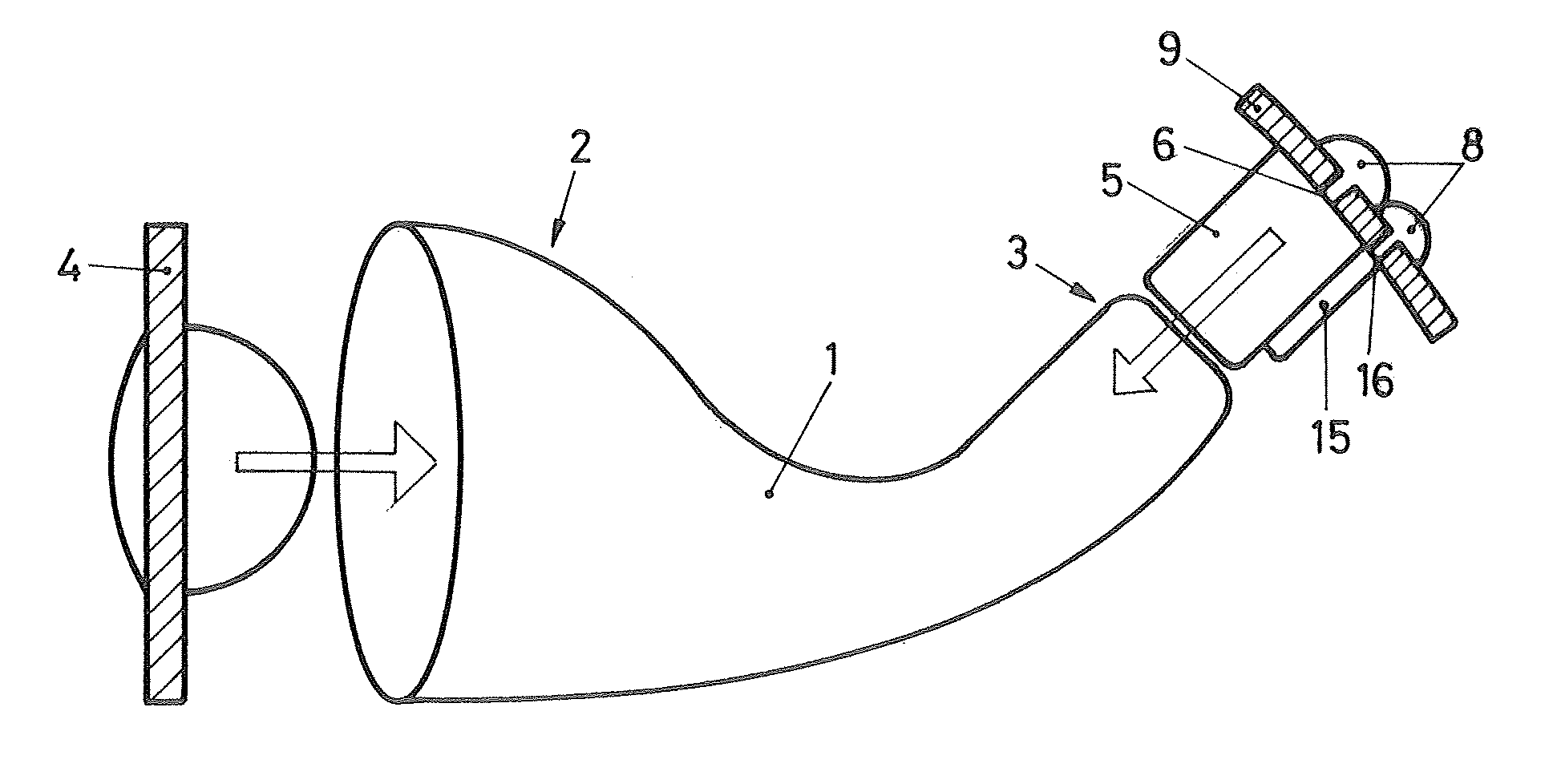
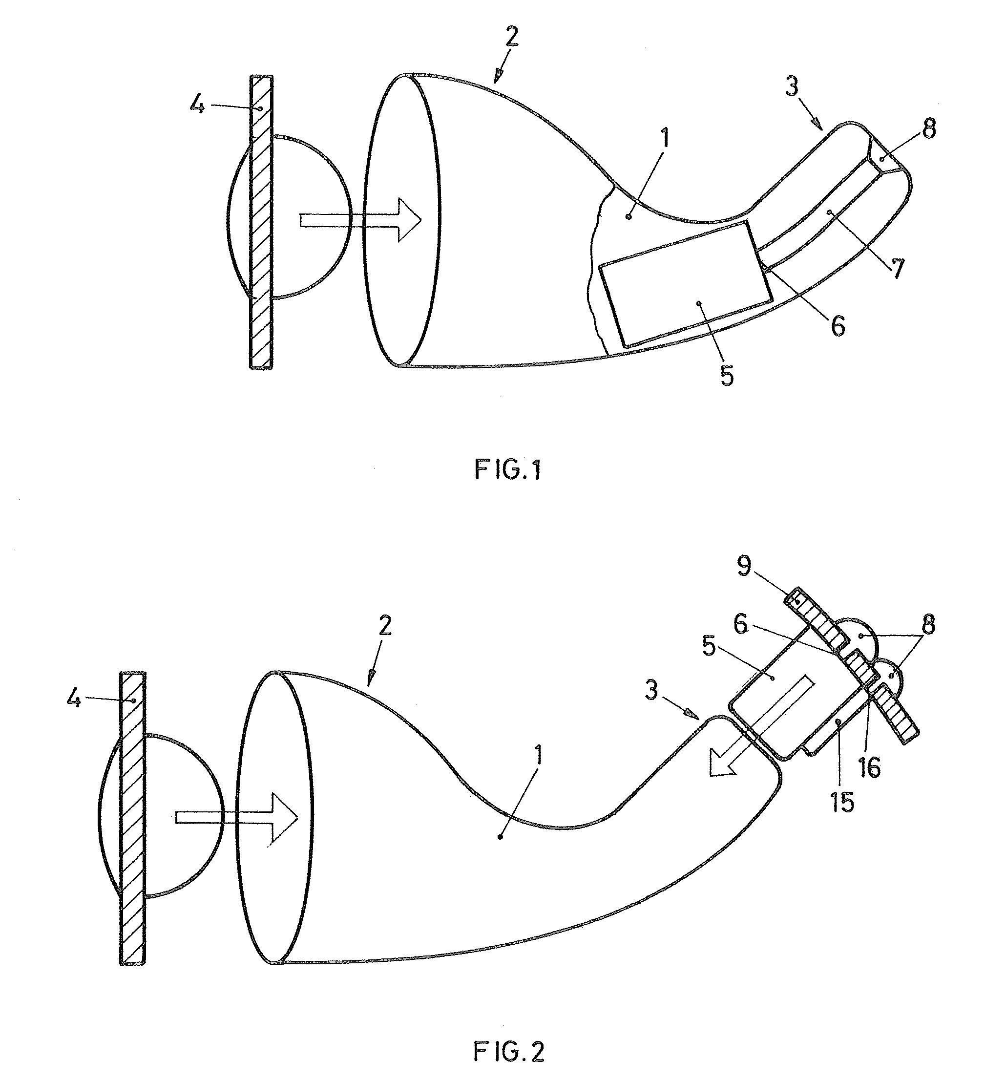
[0047]FIG. 1 shows in a schematic representation a state of the art in-the-ear type hearing device comprising a shell 1 and a face-plate 4 to be attached to the distal end 2 of the shell 1. The shell 1 houses a receiver module 5 along with further components such as for instance a battery and electronic circuitry for audio signal processing and amplification. The sound output port 6 of the receiver module 5 is connected to a sound opening at the proximal end 3 of the shell 1 via an acoustic tube 7. The proximal sound opening is covered by a wax protection member 8 (also referred to as wax guard), which helps to avoid soiling of the receiver and the acoustic tube 7 by ear wax, sweat, etc. The receiver module 5 is conventionally inserted into the shell 1 through an opening at the distal end 2 of the shell 1. The final position of the receiver module 5 within the shell 1 is determined by the individual shape of the shell 1 and the positioning of the remaining components within the shel...


PUM

PropertyMeasurementUnit
colouraaaaaaaaaa
shapeaaaaaaaaaa
sizeaaaaaaaaaa

Abstract

The present invention provides a tip-plate assembly for arrangement at a proximal end portion of a hearing device to be worn at least partially within an ear canal such that said proximal end portion faces towards an ear drum. Said tip-plate assembly comprises a tip-plate (9) having a seating aperture (10), a receiver module (5) having a sound output port (6) at a front end (11), and a suspension element (12). Said suspension element (12) at least partly envelopes said receiver module (5) at said front end (11) and said receiver module (5) is mounted in said seating aperture (10) by means of said suspension element (12). Said tip-plate assembly may further comprise a microphone module (15). Moreover, a hearing device comprising such a tip-plate assembly is given, and a method of manufacturing a hearing device comprising such a tip-plate assembly is proposed.

Description

TECHNICAL FIELD[0001]The present invention relates to hearing devices for being worn at least partially within an ear canal. More specifically the present invention pertains to a tip-plate assembly intended for use with such a hearing device, a hearing device with such a tip-plate assembly as well as a method of manufacturing a hearing device with such a tip-plate.BACKGROUND OF THE INVENTION[0002]In the context of the present invention the term “hearing device” refers to hearing aids (alternatively called hearing instruments or hearing prostheses) used to compensate hearing impairments of hard of hearing persons as well as audio and communication devices used to provide sound signals to persons with normal hearing capability, e.g. in order to improve hearing in harsh acoustic surroundings. Moreover, it also encompasses ear-level hearing protection devices, which safeguard a user from damaging his sense of hearing when subjected to severe acoustic shock events such as for instance gu...

Claims


Application Information

Patent Timeline
Patent Type & Authority Patents(United States)
IPC IPC(8): H04R25/00H04R31/00
CPCH04R25/652H04R25/658H04R31/00H04R25/604H04R25/608H04R2225/025Y10T29/49005H04R25/603H04R25/609
Inventor BAER, DANIELHUG, ROLANDMEYER, JONAS
Owner SONOVA AG
Why Eureka
Try Eureka