
Dual circulation drilling system

a drilling system and circulation technology, applied in the direction of drilling rods, drilling pipes, borehole/well accessories, etc., can solve the problems of not finding favour in oil and gas exploration or production, and increasing the frequency of tripping of associated drill strings, so as to facilitate the killing of wells and high specific gravity

Active Publication Date: 2016-04-19
STRADA DESIGN
View PDF14 Cites 0 Cited by
  • Summary
  • Abstract
  • Description
  • Claims
  • Application Information

AI Technical Summary

Benefits of technology

The patent describes a drilling system and method that uses two fluids to operate a down the hole drilling tool and control downhole pressure conditions. This can improve efficiency and safety while drilling in oil and gas exploration or production. The system also allows for the killing of a well by pumping a second fluid with a high specific gravity through a flow path. The use of a down the hole hammer is often limited due to the compromise between efficiency and safety, but the system can help resolve this issue and lower drilling costs due to down time.

Problems solved by technology

While downhole hammers are used extensively in hard ground conditions they do not find favour in oil and gas exploration or production.
The best fluid for operating the hammer is not often the best fluid for maintaining or controlling downhole pressure conditions and maintaining hole stability.
Conversely the best fluid to maintain or control downhole pressure conditions often has a high specific gravity and additives which, if used to operate a down the hole hammer would accelerate wear.
This means that the associated drill string needs to be tripped more regularly.
In turn this significantly increases drilling costs due to down time.

Method used


Image

  • Dual circulation drilling system
  • Dual circulation drilling system
  • Dual circulation drilling system

Examples


Embodiment Construction

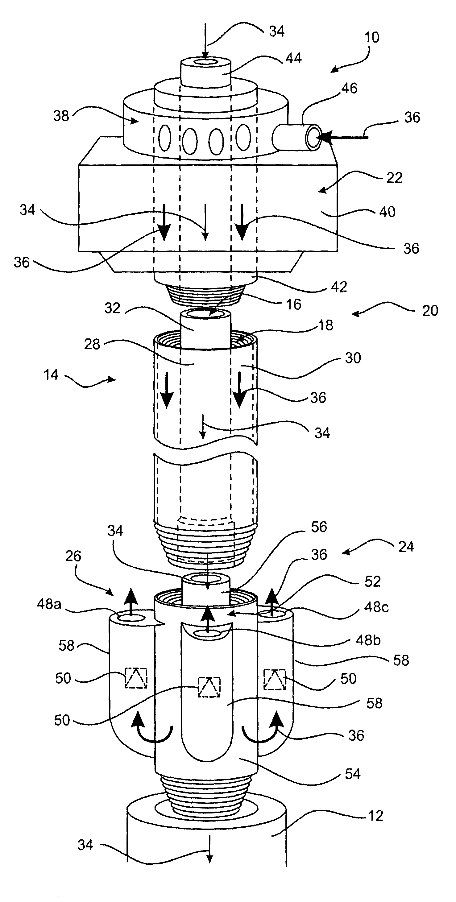
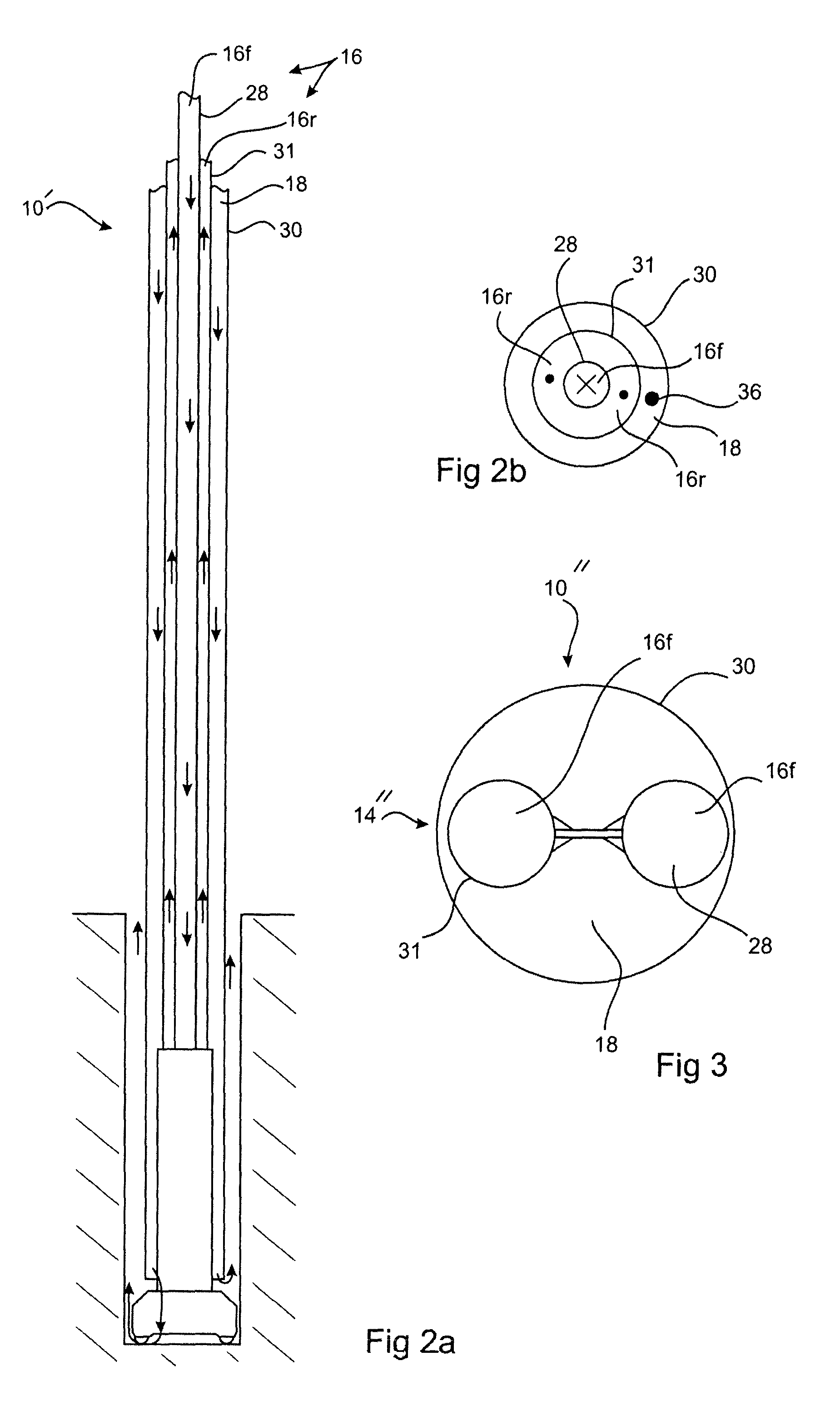
[0084]FIG. 1 provides a schematic representation of ground drill system 10 (hereinafter referred to in general as “drill system 10”). As will be explained in greater detail herein below, the drill system 10 enables the delivery of first and second fluids down a hole or well being drilled by the drill system 10. One of the fluids is used to operate a drilling tool 12 such as a water hammer while the other fluid is released into the hole upstream of the drilling tool 12. The combination of the two fluids can enable: drill cuttings to be brought to the surface; control over hydrostatic pressure to provide a desired over balanced or under balanced drilling conditions, or indeed the ability to change for one to the other; optimum operation and service life of the drilling tool; and maintenance of hole stability. By virtue of the use of the two fluids the system 10 may be described as a dual circulation well control system.

[0085]This embodiment of the system 10 comprises a drill string 14...


PUM


Abstract

A ground drill system (10) has a drill string 14 which forms first and second mutually isolated fluid paths (16 and 18) respectively. The drill string (14) has an up hole end (20) coupled to a dual circulation rotation head (22) and a down hole end (24) which is coupled to a drilling tool (12). The drilling tool (12) is operated by the flow of fluid delivered through the first flow path (16). A second fluid outlet (26) is provided intermediate the up hole end (20) and the drilling tool (12). The outlet (26) is in fluid communication with the second fluid flow path (18) and located a constant or fixed distance from the drilling toll (2). The second fluid outlet (26) discharges a flushing fluid flowing through the flushing flow path (18) into a hole being drilled by the drilling system (10). The rotation head (22) provides torque to the drill string (14) and thus the drilling tool (12).

Description

TECHNICAL FIELD[0001]A system and method are disclosed for drilling a hole in the ground for example exploration or production holes.BACKGROUND ART[0002]Many types of ground drilling systems are available for drilling holes for particular purposes and in specific ground conditions. One range of down hole drill systems utilise a fluid under pressure to assist in advancing the drill. The fluid may act to either drive a drilling tool coupled to an associated drill string, or to flush drill cuttings from a hole being drilled, or both. The fluid can be gas such as air or nitrogen, a liquid / slurry such as water or drilling mud, or a combination of gas and liquid.SUMMARY OF THE DISCLOSURE[0003]In broad terms a drilling system and method are disclosed in which a first fluid is used to operate a down the hole drilling tool, while a second fluid is used to assist in the drilling process, the fluids being isolated from each other while at least flowing down the hole. This assistance includes b...

Claims


Application Information

Patent Timeline
Patent Type & Authority Patents(United States)
IPC IPC(8): E21B21/12E21B1/00E21B4/14E21B17/10E21B17/18E21B7/18E21B21/00E21B21/10
CPCE21B1/00E21B4/14E21B7/18E21B17/1078E21B17/18E21B21/12E21B21/103E21B2021/006E21B21/085E21B1/26E21B21/08E21B21/002
Inventor SPEER, IANSTRANGE, WARREN
Owner STRADA DESIGN
Learn More