System for generating electromagnetic waveforms, subatomic paticles, substantially charge-less particles, and/or magnetic waves with substantially no electric field

a technology of electromagnetic waveforms and magnetic waves, applied in the direction of transit-tube circuit elements, structural circuit elements, cathode-ray/electron beam tube circuit elements, etc., can solve the problems that microwaves are not appropriate or the best practice in every application, and achieve the effect of improving the acceleration of magnetic waves and reducing the plasma field

Inactive Publication Date: 2016-04-05
KAONETICS TECH
View PDF24 Cites 0 Cited by
  • Summary
  • Abstract
  • Description
  • Claims
  • Application Information

AI Technical Summary

Benefits of technology

[0021]The cathode preferably is configured and positioned within the housing to produce an oscillating plasma field which expands and contracts. The cathode has a top surface and an outer side surface, and the magnetron preferably is configured and positioned within the housing such that the top surface of the cathode and the wall above the top surface define an air gap spacing, the plasma being formed in the air gap spacing, and the cathode further being configured and positioned within the housing to define a bleed off spacing gap which reduces the plasma field. Preferably the bleed-off spacing gap is less than the air space gap, and preferably the ratio of the air space gap to the bleed off spacing gap is greater than or equal to about 5:4. Preferably the housing has a top wall, back wall and at least two side walls, and the cathode is positioned within the housing such that it is closest to the back wall and the back wall defines the bleed off spacing gap for quenching of the plasma. Also, preferably the distance from the cathode to the side walls is the same as the distance from the cathode to the top wall. The housing may also include a front wall, and the cathode preferably is positioned within the housing such that the front wall is positioned further from the cathode than the back wall, the side walls or the top wall. In one embodiment, the front wall may be formed of a different material than at least one of the other walls. The housing may further includes a throat section for improving the acceleration of the magnetic wave of no or substantially no electric field current and / or the charge-less or substantially charge-less particles and / or the subatomic particles. The housing may also have an opening, the opening preferably being hermetically sealed with a cover member, and the covering member may be formed of a different material than the housing.

Problems solved by technology

Microwaves, however, are not appropriate or the best practice in every application.

Method used


Image

  • System for generating electromagnetic waveforms, subatomic paticles, substantially charge-less particles, and/or magnetic waves with substantially no electric field
  • System for generating electromagnetic waveforms, subatomic paticles, substantially charge-less particles, and/or magnetic waves with substantially no electric field
  • System for generating electromagnetic waveforms, subatomic paticles, substantially charge-less particles, and/or magnetic waves with substantially no electric field

Examples


Embodiment Construction

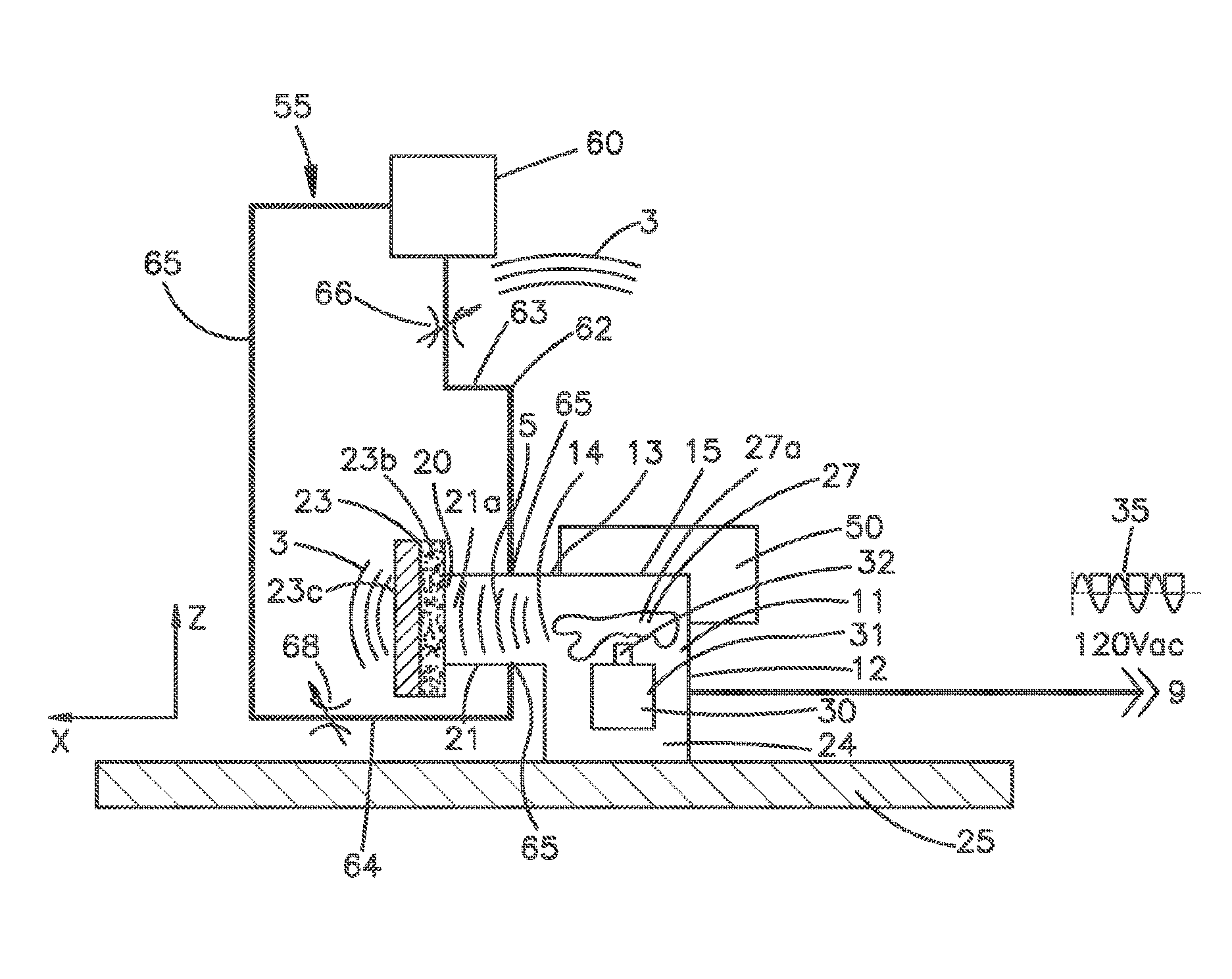
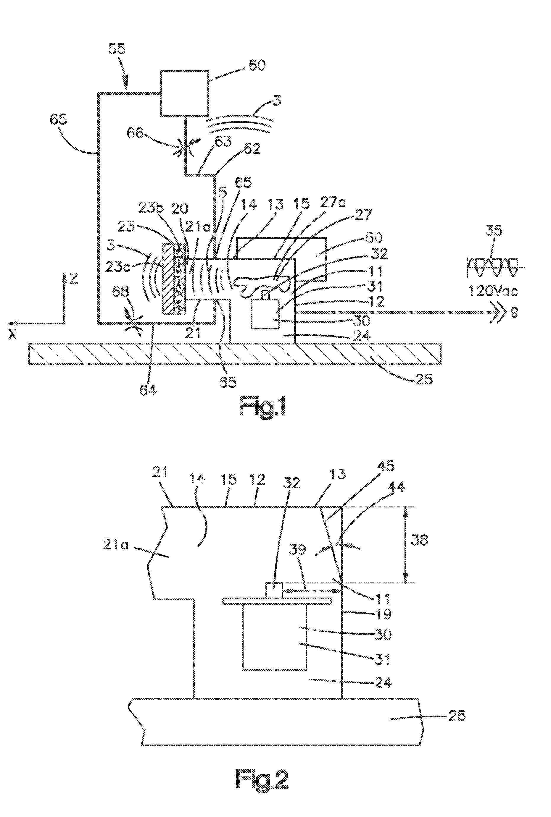
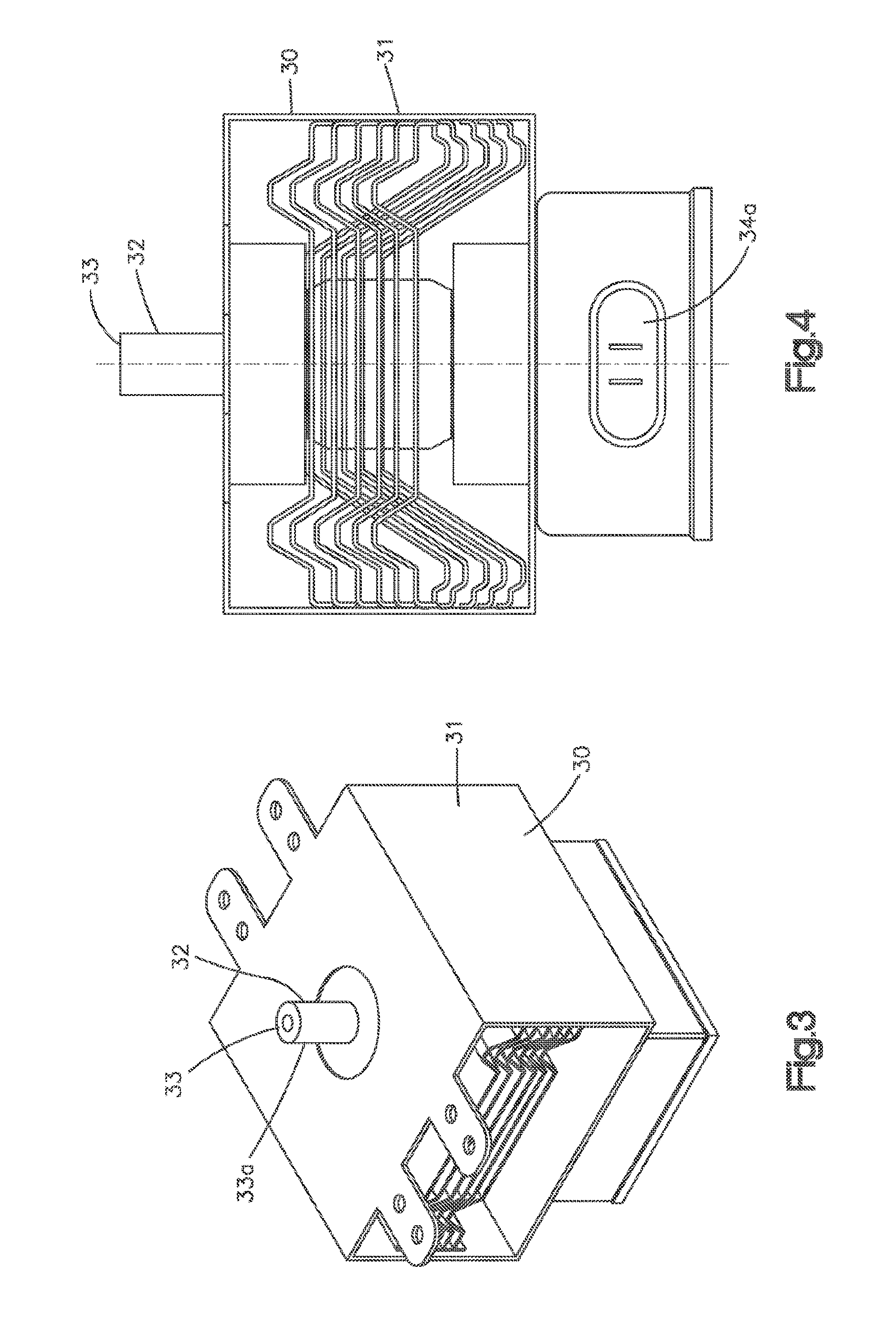
[0036]FIGS. 1, 2, 11 and 12 show exemplary preferred embodiments of an energy generator or directed energy system 10 comprising a housing 12 forming a reaction chamber, cavity or reactor 14. A broad band signal generator 30, such as, for example, an erratically operating microwave magnetron emitter 31, is operatively associated with and preferably mounted to the housing 12 for the formation of broad-band waveforms, including, for example, electro-magnetic waves, radio frequency waves, microwaves, acoustic waves and / or photons, within the housing chamber 14. A power supply 9 preferably supplies the broad-band signal generator 30 with electrical power. In one embodiment, the broad-band signal generator 30 may be a standard microwave magnetron 31. Power supply 9 preferably supplies a dirty alternating current voltage signal 35 to the standard microwave magnetron 31 to facilitate and create the erratic and unstable operation of the microwave magnetron which creates electromagnetic wavef...


PUM


Abstract

The present invention is directed towards devices, systems and methods which produce electromagnetic waveforms including radio-frequency waves, microwaves and electromagnetic waves having no field current or electric field (magnetic waves) and subatomic and / or charge-less particles. In one embodiment, the system and method produces a “charge-less” propagating “magnetic” wave and / or charge-less particles and / or subatomic particles which have demonstrated high utility in the structural modification of both solids and liquids for materials processing. The energy generator according to one embodiment comprises a magnetron emitter hermetically sealed in a housing and supplied with a continuous dirty or erratic voltage signal to cause the magnetron emitter to operate erratically and unstably as a broad band signal generator whereby electromagnetic waves are produced in the hermetically sealed housing which facilitates and produces a plasma above the cathode of the magnetron emitter. The plasma preferably expands and contracts (oscillating) within the housing.

Description

CROSS-REFERENCE TO RELATED APPLICATIONS[0001]This application is continuation of Application No. PCT / US10 / 53826, filed Oct. 22, 2010, which claims the benefit and priority of U.S. Provisional Application No. 61 / 254,449, filed on Oct. 23, 2009 and entitled “Electromagnetic Resonator with Particle Field Isolated from Electromagnetic Waves,” the contents of these applications are incorporated by reference.[0002]This application also incorporates by reference in its entirety PCT / US2008 / 012678 filed Nov. 12, 2008.FIELD OF THE INVENTION[0003]The subject matter of the present invention relates generally to a device, system and method to produce directed-energy including the production of electromagnetic wave forms, including radio frequency waves, microwaves, acoustic waves and / or photons, and in one embodiment subatomic and charge-less particles including a pure magnetic wave with no or substantially no electric field, referred to as a charge-less magnetic wave.BACKGROUND OF THE INVENTION...

Claims


Application Information

Patent Timeline
Patent Type & Authority Patents(United States)
IPC IPC(8): H01J25/50H05H1/46
CPCH05H1/46
Inventor CORNWELL, JAMES
Owner KAONETICS TECH
Why Eureka
Try Eureka