Stator cooling channel tolerant to localized blockage

a cooling channel and local blockage technology, applied in the field of electrical machines, can solve the problems of limiting the range of applications in which the engine may be used, generating a considerable amount of heat during operation, and reducing the life and performance of the motor and generator

Active Publication Date: 2016-04-05
HAMILTON SUNDSTRAND CORP
View PDF14 Cites 5 Cited by
  • Summary
  • Abstract
  • Description
  • Claims
  • Application Information

AI Technical Summary

Problems solved by technology

A stator core generates a considerable amount of heat during operation.
It is important to remove this heat because overheating of the stator will reduce the life and performance of motors and generators, thereby limiting the range of applications in which they may be used.
The blockage impedes the flow of the cooling fluid to a portion of the stator, such that heat from that area of the stator is not efficiently removed.
Occurrence of such blockages cause the temperature of the stator to rise and can ultimately lead to a winding failure.

Method used


Image

  • Stator cooling channel tolerant to localized blockage
  • Stator cooling channel tolerant to localized blockage
  • Stator cooling channel tolerant to localized blockage

Examples


Embodiment Construction

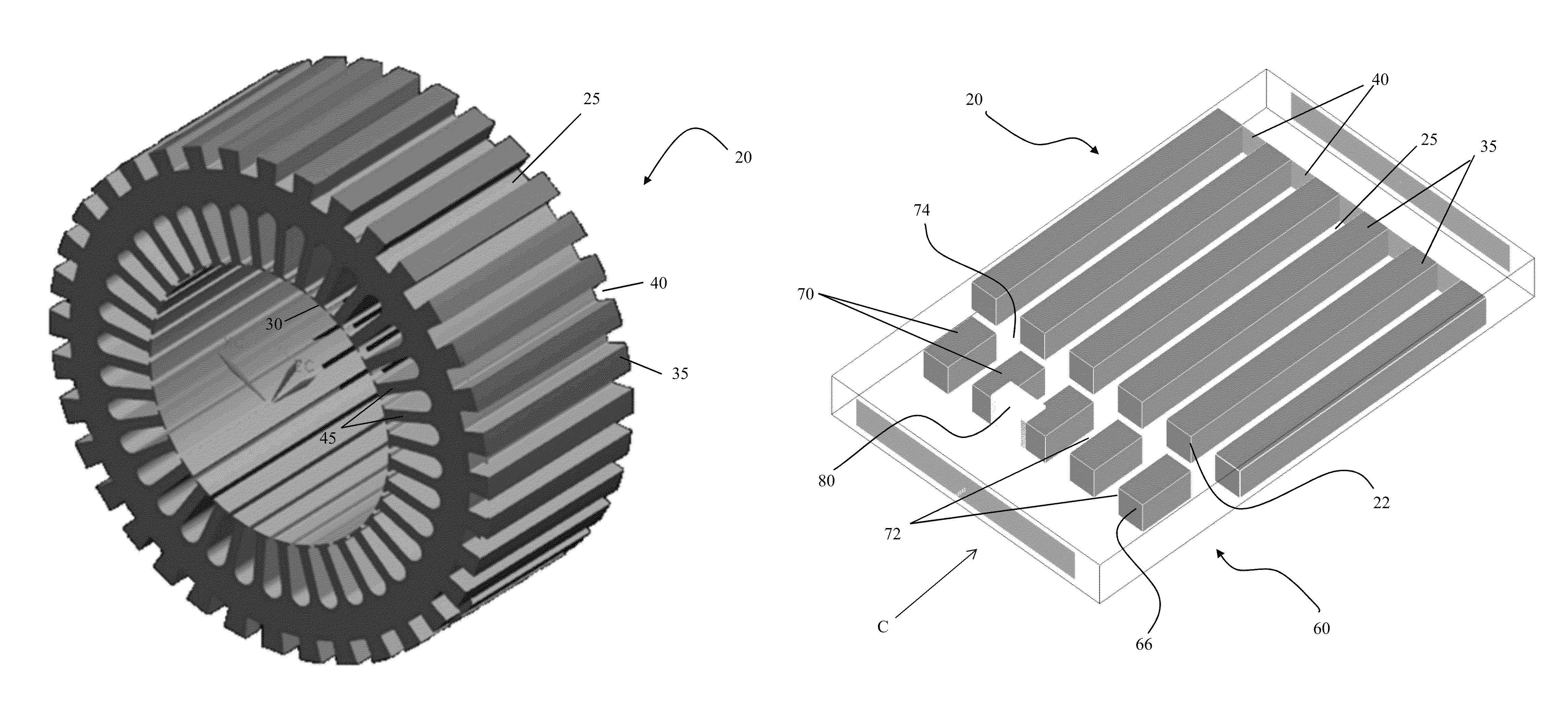
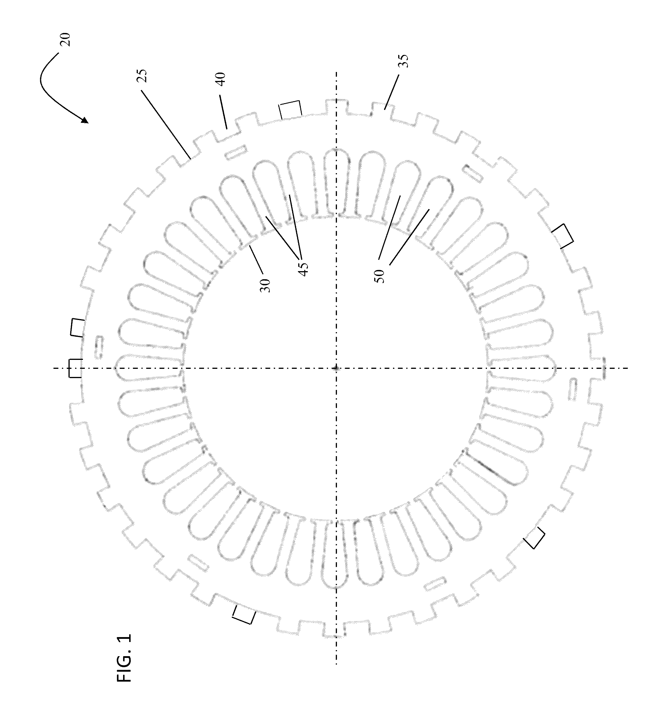
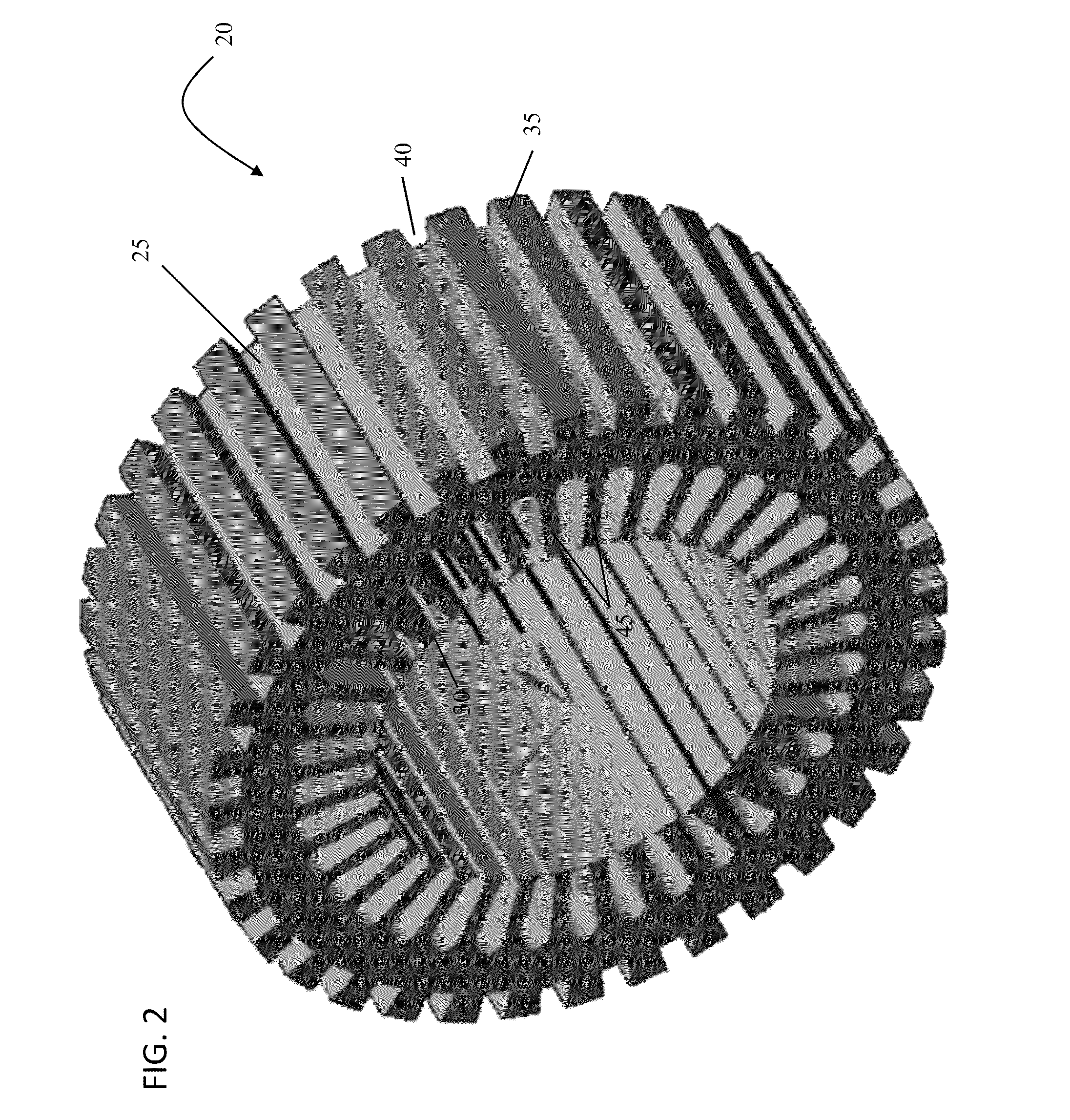
[0014]Referring now to FIGS. 1 and 2, a generally circular stator core 20 of an electrical machine or motor is illustrated. The stator core 20 may be made from iron or any other conventionally used material. The stator core 20 includes a plurality of substantially identical and outwardly projecting fins 35, located around the outside diameter 25 thereof. The fins 35 define an outer periphery of the stator 20. In one embodiment, the fins 35 are uniform in size. A plurality of cooling channels 40 are created between adjacent fins 35 such that a cooling fluid, such as air for example, may flow through the cooling channels 40 to remove heat from the stator core 20. The stator core 20 also includes a plurality of inwardly projecting teeth 45 that define an inner periphery 30 of the stator core 20. The teeth 45 also provide winding spaces 50 that receive the stator windings (not shown) of the stator core 20.

[0015]As is known in the art, electrical machines typically include a rotor dispos...


PUM


Abstract

A motor is provided including a stator core having a plurality of stator fins projecting outwardly from the stator core. A plurality of stator cooling channels is defined between adjacent stator fins. A flow mixer ring is axially aligned with the stator core and separated therefrom by an axial gap. The flow mixer ring includes a plurality of ring fins projecting inwardly from an interior surface and a plurality of ring cooling channels defined between the plurality of ring fins. The plurality of ring fins extends from a first surface over at least a portion of an axial length of the flow mixer ring.

Description

BACKGROUND OF THE INVENTION[0001]Exemplary embodiments of this invention generally relate to electrical machines and, more particularly, to a stator structure of an electrical machine for improved cooling.[0002]A stator core generates a considerable amount of heat during operation. It is important to remove this heat because overheating of the stator will reduce the life and performance of motors and generators, thereby limiting the range of applications in which they may be used. Conventional stators include a plurality of fins disposed around the outside circumference of the stator. A cooling fluid, such as air, oil, or another coolant for example, will flow through the cooling channels created between adjacent fins to remove heat from the stator through convection.[0003]In some applications, foreign material from the environment, such as dirt and debris, will enter the stator assembly. This foreign material may become lodged in the stator assembly so as to form a blockage in one ...

Claims


Application Information

Patent Timeline
Patent Type & Authority Patents(United States)
IPC IPC(8): H02K9/06H02K1/20
CPCH02K9/06H02K1/20H02K2213/03
Inventor COLDWATE, JOSEPH KENNETHBECK, JOHN M.PAL, DEBABRATALUCIC, MILAN
Owner HAMILTON SUNDSTRAND CORP
Why Eureka
Try Eureka