
Article storage facility and article storage method

a technology for storage facilities and articles, applied in the field of article storage facilities, can solve problems such as the inability to normal operation of facilities, and achieve the effect of preventing deterioration of conditions

Active Publication Date: 2016-02-23
DAIFUKU CO LTD
View PDF15 Cites 9 Cited by
  • Summary
  • Abstract
  • Description
  • Claims
  • Application Information

AI Technical Summary

Benefits of technology

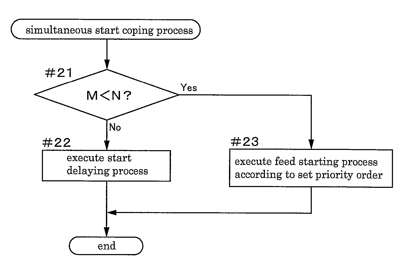
[0019]With the above-described arrangement, with execution of the start delaying process, it is possible to avoid a situation wherein the command for controlling to the first feed state is issued at one time to a number of inactive gas feeding sections which number exceeds the maximum simultaneous feed number. As a result, it becomes possible to avoid the situation of the flow rate of inactive gas for the inactive gas feeding section falling short of the first flow rate as the target flow rate, whereby the facility can be operated normally.
[0059]With the above-described arrangement, for those delaying process target feeding sections having long periods from the start of the start delaying process, further delaying of start of the first feed state can be avoided, so that the deterioration of the condition inside the transport container can be restricted appropriately.

Problems solved by technology

Therefore, even when commanded the first flow rate as the target flow rate, the flow rate adjusting device will be unable to adjust the feed flow rate of inactive gas to this target flow rate, whereby there will occur inconvenience that the inactive gas feeding section can feed the inactive gas only by a flow rate below the target flow rate.
In the case of using a flow rate adjusting device having such function as above, as described above, if the condition of the flow rate of inactive gas that can be actually fed to each transport container falling short of the first flow rate as the target flow rate has continued for a set period, an error will issue, so that the normal operation of the facility may become impossible.

Method used


Image

  • Article storage facility and article storage method
  • Article storage facility and article storage method
  • Article storage facility and article storage method

Examples


Embodiment Construction

[0087]Next, embodiments of the present invention as being applied to an article storage facility with a purging function will be explained with reference to the accompanying drawings.

(General Construction)

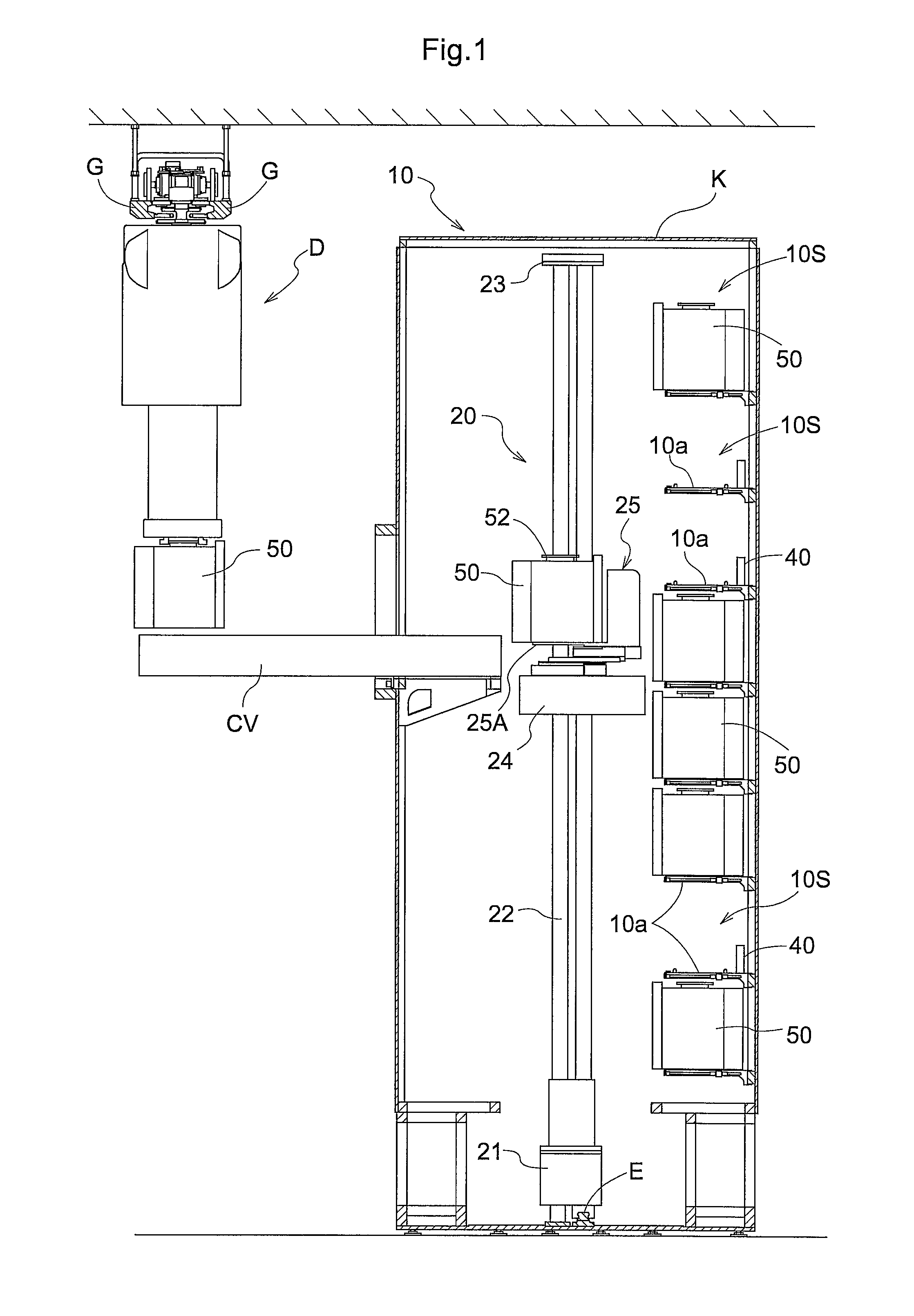
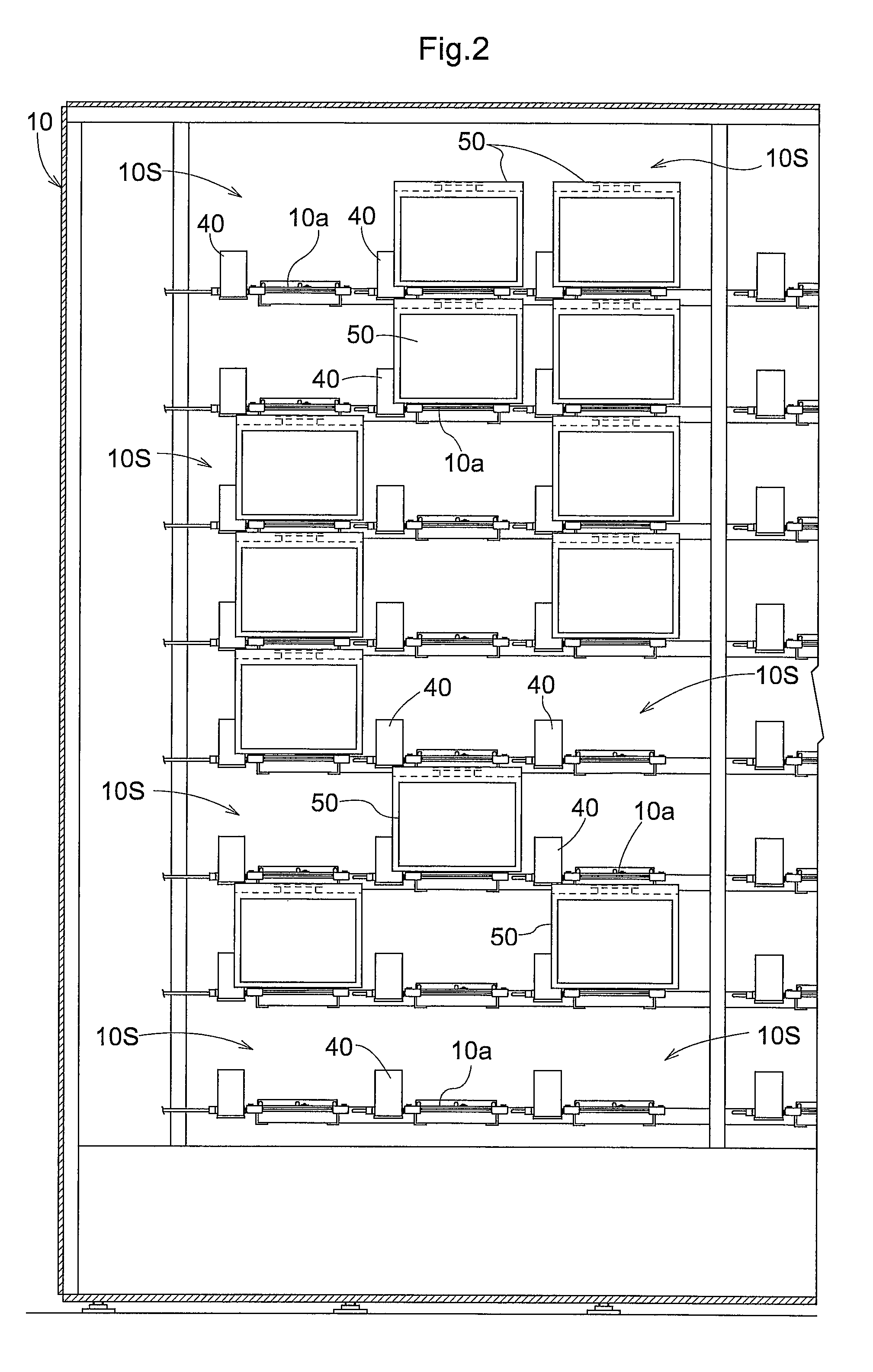
[0088]An article storage facility, as shown in FIG. 1 and FIG. 2, includes a storage shelf 10 for storing transport containers 50 (to be referred to shortly as “containers 50” hereinafter) each accommodating a substrate therein under a sealed state, a stacker crane 20 as a transport device, and a carry in / out conveyor CV as a carry in / out section for the containers 50.

[0089]The storage shelf 10 and the stacker crane 20 are disposed in an installment space having its outer periphery covered with a wall body K and the carry in / out conveyor CV is disposed to extend through the wall body K.

[0090]The storage shelf 10 includes a plurality of storage sections 10S, as support portions for supporting the containers 50, juxtaposed along the vertical direction and the right / left direction, ea...


PUM


Abstract

When a controller determines that the maximum simultaneous feed number is exceeded by a total target number which is the total number of inactive gas feeding section determined to be controlled to the first feed state at one time, of the inactive gas feeding sections determined to be controlled to the first feed state at one time, the controller controls some of them not more than the maximum simultaneous feed number to the first feed state and executes a start delaying process for the others in which process starting of the first control state is delayed by a set delay period.

Description

FIELD OF THE INVENTION[0001]The present invention relates to an article storage facility including a plurality of storage sections each storing therein a transport container accommodating a substrate therein, a transport device for transporting the transport containers to the plurality of storage sections, an inactive gas feeding section for feeding an inactive gas to the inside of the transport container accommodated in the storage section, and a controller for controlling the operation of the transport device and the operation of a flow rate adjusting device of the inactive gas feeding section. The invention relates also to an article storage method utilizing such article storage facility.BACKGROUND[0002]As an example of such article storage facility described above, there is known an article storage facility having an article storage shelf with a purging function described below. This article storage shelf includes a plurality of storage sections for storing a transport container...

Claims


Application Information

Patent Timeline
Patent Type & Authority Patents(United States)
IPC IPC(8): H01L21/67B65B5/00H01L21/677H01L21/673
CPCB65B5/00H01L21/67393H01L21/67769B65G1/0414H01L21/6773H01L21/67733
Inventor TAKAHARA, MASAHIROUEDA, TOSHIHITO
Owner DAIFUKU CO LTD
Learn More