
Control apparatus of rolling mill

a control apparatus and rolling mill technology, applied in the direction of rolling mill control devices, metal rolling arrangements, manufacturing tools, etc., can solve the problems of periodic roll gap variations dependent on the rotation of the roll, shaft movement up and down (undergo shaft oscillation), and the thickness accuracy of the harrowing improvement, etc., to achieve the effect of suppressing periodic disturbances

Active Publication Date: 2016-01-26
TOSHIBA MITSUBISHI-ELECTRIC IND SYST CORP
View PDF8 Cites 1 Cited by
  • Summary
  • Abstract
  • Description
  • Claims
  • Application Information

AI Technical Summary

Benefits of technology

[0022]According to the control apparatus of a rolling mill of this invention, it becomes possible to appropriately suppress periodic disturbances caused by roll eccentricity and the like in the gauge control during the rolling of a metal material, and furthermore, to realize high-accuracy gauge control also in the rolling of an extreme leading end of a rolled material.

Problems solved by technology

For example, in the case of hot rolling, temperature variations of rolled materials can be mentioned as disturbances which hinder an improvement in thickness accuracy.
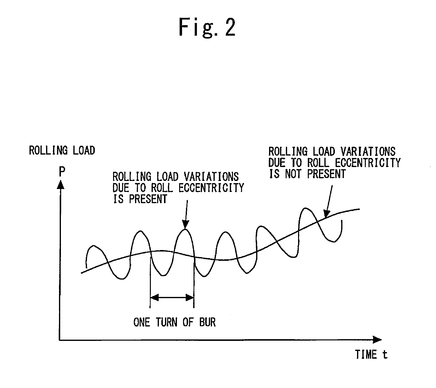
Among these disturbances, the main cause of the above-described roll eccentricity is that when key grooves of support rolls having oil bearings are subjected to a rolling load of as large as several hundreds of tons to two to three thousands of tons, shafts move up and down (undergo shaft oscillation).
Even in the case of rolls not provided with key grooves, periodic roll gap variations dependent on the rotation of the rolls occur caused by asymmetry during roll grinding and uneven thermal expansion, for example.
However, disturbances dependent on the shaft oscillation of rolls, such as roll eccentricity, cannot be detected by a roll gap detector.
For this reason, it is impossible to perform such control as to suppress the disturbances dependent on the shaft oscillation of rolls even when a roll gap detector is used.
However, because in actuality, the disturbances dependent on the shaft oscillation of rolls change roll gaps, the effect of the shaft oscillation of rolls manifests itself in rolling loads.

Method used


Image

  • Control apparatus of rolling mill
  • Control apparatus of rolling mill
  • Control apparatus of rolling mill

Examples


first embodiment

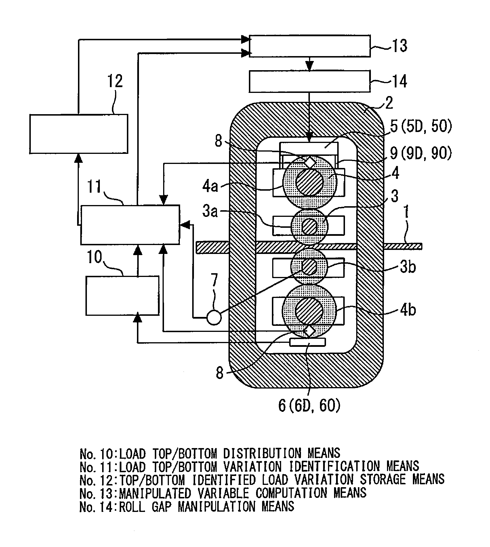
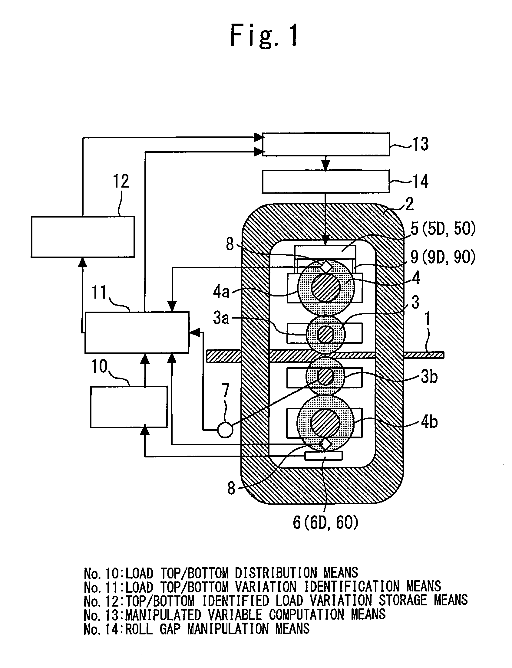
[0039]FIG. 1 is a diagram showing the general configuration of a control apparatus of a rolling mill in a first embodiment according to the present invention.

[0040]In FIG. 1, reference numeral 1 denotes a rolled material, which is made of a metal material, reference numeral 2 denotes a housing of a rolling mill, reference numeral 3 denotes a work roll, and reference numeral 4 denotes a back up roll. The rolled material 1 is rolled by the work rolls 3 whose roll gaps and speeds are appropriately adjusted so that a desired thickness is obtained on the exit side of the rolling mill.

[0041]In FIG. 1, a 4Hi mill is shown as an example of a rolling mill. That is, in this embodiment, the work roll 3 includes a top work roll 3a and a bottom work roll 3b. The back up roll 4 includes a top back up roll 4a and a bottom back up roll 4b. The work roll 3 is configured in such a manner as to be supported by the back up roll 4 so that deflection in the roll width direction becomes small. Specificall...

second embodiment

[0118]FIG. 9 is a diagram showing the general configuration of a control apparatus of a rolling mill in a second embodiment according to the present invention.

[0119]In FIG. 9, reference numeral 27 denotes roll gap top / bottom variation identification means, reference numeral 28 denotes top / bottom identified roll gap variation storage means, and reference numeral 29 denotes manipulated variable computation means.

[0120]In the first embodiment, the description was given of the case where load signals are accumulated in the adders 26a and 26b of the load top / bottom variation identification means 11. However, the rolling load sometimes shows changes in the amplitude of variations depending on the width, deformation resistance (hardness) and the like of the rolled material 1. Therefore, in this embodiment, a description will be given of the case where a load signal is converted to a value corresponding to a roll gap and then, accumulated to the adder. With this configuration, it becomes po...

third embodiment

[0135]FIG. 12 is a diagram showing the rolling mill shown in FIG. 1 as viewed from the rolling direction of a rolled material.

[0136]There are cases where roll gap variation components caused by the roll eccentricity and the like are not the same on the right and left sides of the rolled material 1, i.e., on the drive side and the operator side of the rolled material 1, for example, in the case where the construction of oil bearings used in the back up roll 4 is laterally asymmetrical. This control apparatus is provided with the screw-down device 5, the load detecting device 6, and the roll gap detector 9 on both the drive side and the operator side, and the mechanism of this control apparatus are such that a roll gap can be separately controlled on the drive side and the operator side. For this reason, in this embodiment, a description will be given of the case where on the drive side and the operator side, variation components due to periodic disturbances are separately identified ...


PUM

PropertyMeasurementUnit
rotational angleaaaaaaaaaa
thicknessaaaaaaaaaa
displacementaaaaaaaaaa

Abstract

A control apparatus of a rolling mill includes a load top / bottom distributor distributing loads as top and bottom side loads, a load top / bottom variation identification mechanism identifying load variation components occurring in connection with a rotational position of rolls from the top and bottom side loads, and top / bottom identified load variation storage storing, for each rotational position of rolls, top and bottom side variation components of the load in a kiss-roll condition identified by the load top / bottom variation identification mechanism. A manipulated variable computer computes a roll gap instruction value based on the top and bottom side variation components of the rolling load identified by the load top / bottom variation identification mechanism, and the top side variation component and the bottom side variation component of the load in a kiss-roll condition stored in the top / bottom identified load variation storage.

Description

TECHNICAL FIELD[0001]The present invention relates to a control apparatus for reducing periodic disturbances, for example, load variations which periodically occur with respect to the rotation position of rolls and the like and gauge variations which occur as a result of the load variations, in the gauge control during the rolling of a metal material.BACKGROUND ART[0002]One of quality control methods in sheet rolling and plate rolling is automatic gauge control (AGC) which involves controlling the plate thickness of a rolled material in the middle part of the width direction. Examples of concrete control methods include monitor AGC which involves feeding back measured values of a plate thickness gauge installed on the exit side of a rolling mill, gauge meter AGC (GM-AGC) which involves using gauge meter plate thicknesses estimated from rolling loads and roll gaps (the clearance between top and bottom work rolls), and mill modulus control (MMC) which involves using rolling loads.[000...

Claims


Application Information

Patent Timeline
Patent Type & Authority Patents(United States)
IPC IPC(8): B21B37/18B21B37/66B21B37/16B21B37/62
CPCB21B37/18B21B37/66B21B37/16B21B37/62B21B2265/12B21B2271/02B21B37/00
Inventor IMANARI, HIROYUKIKAWAMURA, SHIGEOMARUYAMA, KAZUYUKI
Owner TOSHIBA MITSUBISHI-ELECTRIC IND SYST CORP
Learn More