
Approach to adjust driving waveforms for a display device

a display device and driving waveform technology, applied in the field of electrotrophoretic display, can solve the problems of slow image change, lack of bistability, and inability to obtain full contras

Active Publication Date: 2015-12-29
E INK CORPORATION
View PDF98 Cites 131 Cited by
  • Summary
  • Abstract
  • Description
  • Claims
  • Application Information

AI Technical Summary

Problems solved by technology

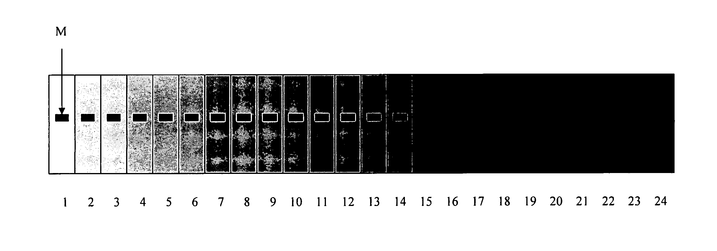
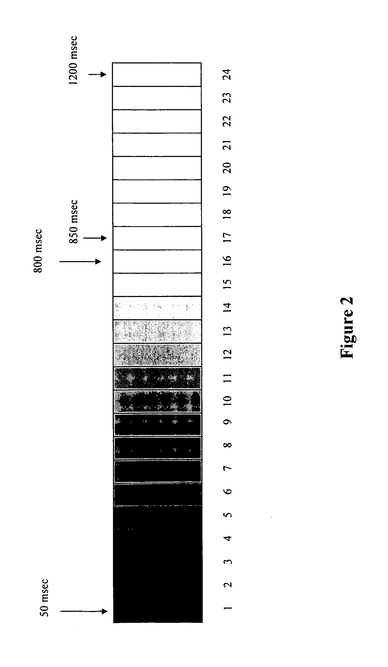
It is important that the waveform lengths are optimized in the binary image system because driving the display medium too short a time results in not obtaining full contrast and also in lack of bistability.
Driving it too long, on the other hand, can result in slow image changes and poor bistability.

Method used


Image

  • Approach to adjust driving waveforms for a display device
  • Approach to adjust driving waveforms for a display device
  • Approach to adjust driving waveforms for a display device

Examples


Embodiment Construction

[0071]The present invention is directed to methods for adjusting or selecting driving waveforms (e.g., the timing of waveforms) in order to achieve a consistent optical performance of a display device. When a method of the present invention is applied, even if there are changes in the display medium due to temperature variation, photo-exposure or aging, the optical performance can be maintained at a desired level.

[0072]While electrophoretic displays are specifically mentioned in this application, it is understood that the present invention is applicable to any reflective, transmissive or emissive displays, such as liquid crystal displays, polymer-dispersed liquid crystal displays, electrochromic displays, electrodeposition displays, liquid toner displays, plasma displays, LED displays, OLED displays, field emission displays or the like. The display medium varies, depending on the type of displays involved.

[0073]As the optical response speed changes due to photo-exposure, temperature...


PUM


Abstract

The present invention is directed to methods for adjusting or selecting driving waveforms in order to achieve a consistent optical performance of a display device. When a method of the present invention is applied, even if there are changes in the display medium due to temperature variation, photo-exposure or aging, the optical performance can be maintained at a desired level.

Description

[0001]This application claims the benefit of U.S. Provisional Application No. 60 / 979,708, filed Oct. 12, 2007; which is incorporated herein by reference in its entirety.FIELD OF THE INVENTION[0002]An electrophoretic display is a device based on the electrophoresis phenomenon of charged pigment particles dispersed in a solvent. The display usually comprises two electrode plates placed opposite of each other and a display medium comprising charged pigment particles dispersed in a solvent is sandwiched between the two electrode plates. When a voltage difference is imposed between the two electrode plates, the charged pigment particles may migrate to one side or the other, depending on the polarity of the voltage difference, to cause either the color of the pigment particles or the color of the solvent to be seen from the viewing side of the display.[0003]One of the factors which determine the performance of an electrophoretic display is the optical response speed of the display, which ...

Claims


Application Information

Patent Timeline
Patent Type & Authority Patents(United States)
IPC IPC(8): G09G3/34G09G3/20
CPCG09G3/344G09G3/20G09G2320/041G09G2360/145G09G2320/0606G09G2320/066G09G2320/0693G09G2320/043
Inventor LIN, CRAIG
Owner E INK CORPORATION
Learn More