
Vehicular camera system with reduced number of pins and conduits

a technology of camera system and conduit, which is applied in the field of vehicle camera system, can solve the problems of affecting the size of the camera, the cost of the camera, and the number of camera components, and adds to the overall cost of the camera

Active Publication Date: 2015-12-08
MAGNA ELECTRONICS INC
View PDF28 Cites 34 Cited by
  • Summary
  • Abstract
  • Description
  • Claims
  • Application Information

AI Technical Summary

Benefits of technology

The solution results in a smaller, less expensive camera system with enhanced electromagnetic compatibility and reduced wiring complexity, enabling efficient programming and tracking without compromising image quality.

Problems solved by technology

As a result, the connector directly impacts the size of the camera, the number of components in the camera, and the cost of the camera.
Additionally, the wiring that extends from the connector to points in the vehicle such as a display in the instrument panel and a vehicle ground adds to the overall cost associated with the camera.

Method used


Image

  • Vehicular camera system with reduced number of pins and conduits
  • Vehicular camera system with reduced number of pins and conduits
  • Vehicular camera system with reduced number of pins and conduits

Examples


Embodiment Construction

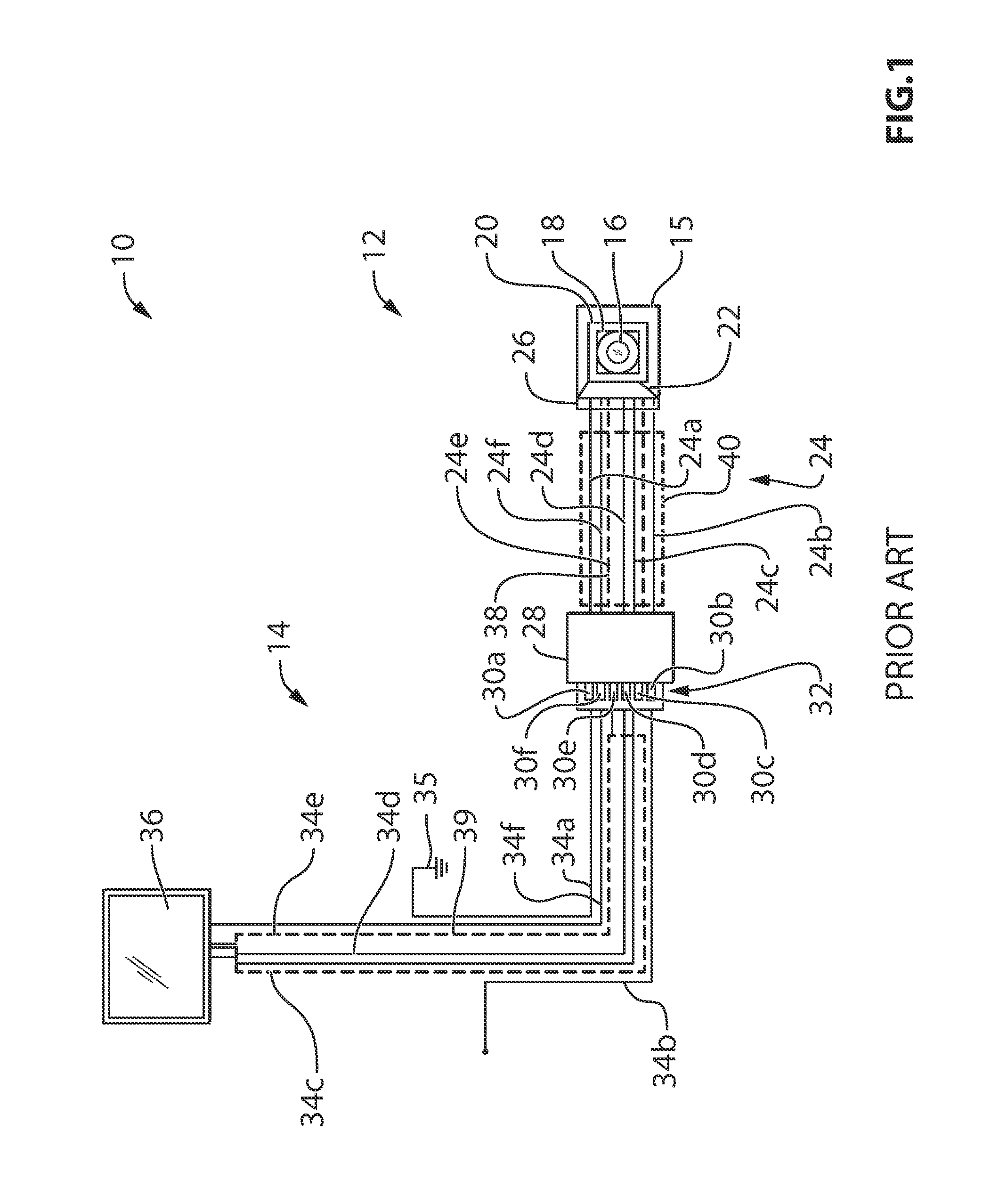
[0017]Reference is made to FIG. 1, which shows a vehicular camera system 10 in accordance with the prior art. The vehicular camera system 10 includes a vehicle camera assembly 12 and a vehicle conduit assembly 14 connecting the camera assembly 12 to several points in a vehicle. The vehicle camera assembly 12 includes a housing 15, a lens 16, an imager 18, a printed circuit board 20, a printed circuit board connector 22 on the printed circuit board 20, a set of conduits 24 with an intermediate connector 26 at a first end for connecting to the printed circuit board connector 22 and with an end connector 28 at a second end for connecting to the vehicle conduit assembly 14. Each of the connectors 22, 26 and 28 in the camera assembly 12 has 6 connection points (i.e. pins or receptacles), including: ground 30a, power 30b, video+30c, video−30d, video shield 30e, and an optional communication connection point 30f for connecting to a bus such as a CAN bus or a LIN bus.

[0018]The conduits 24 c...


PUM


Abstract

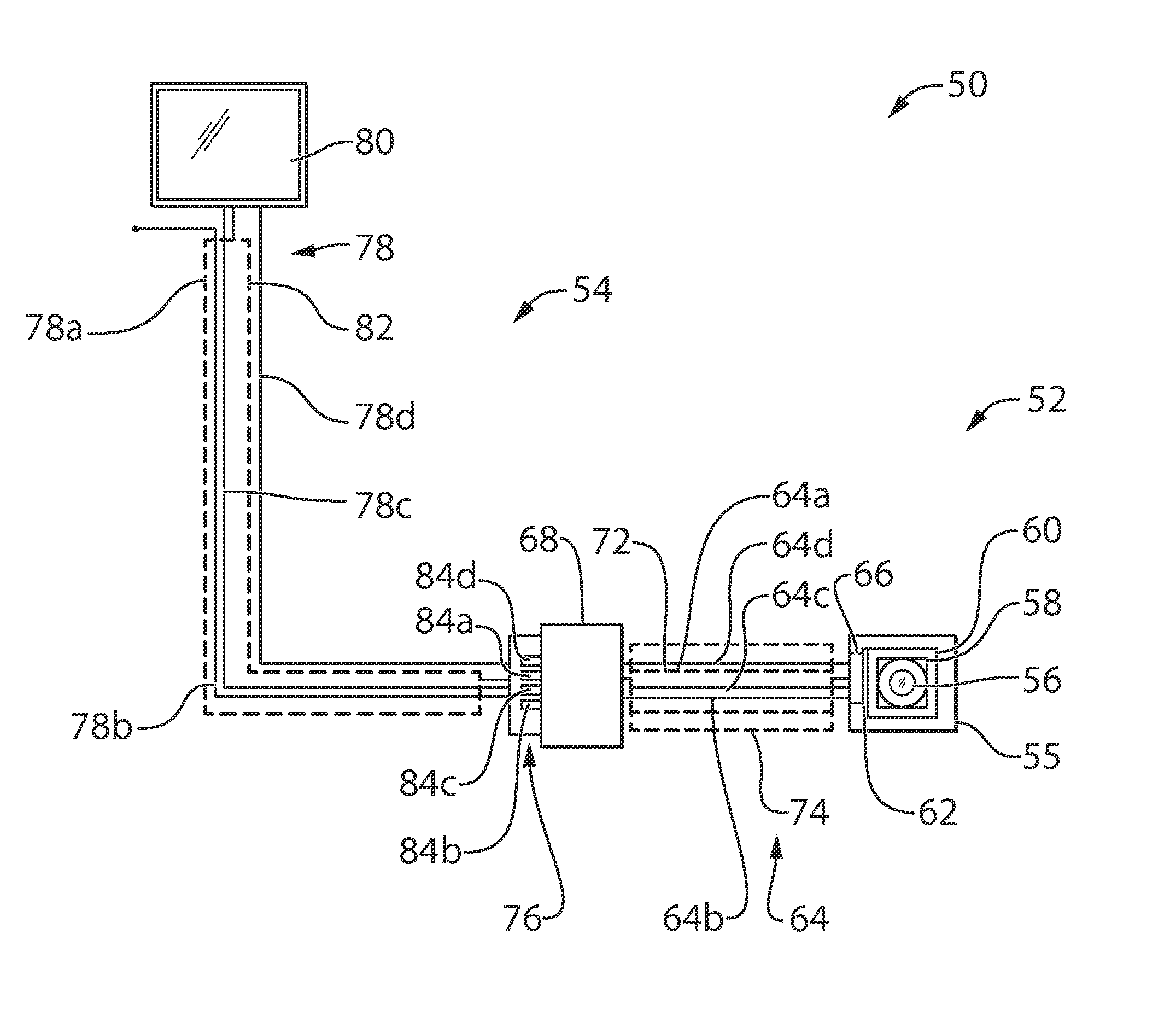
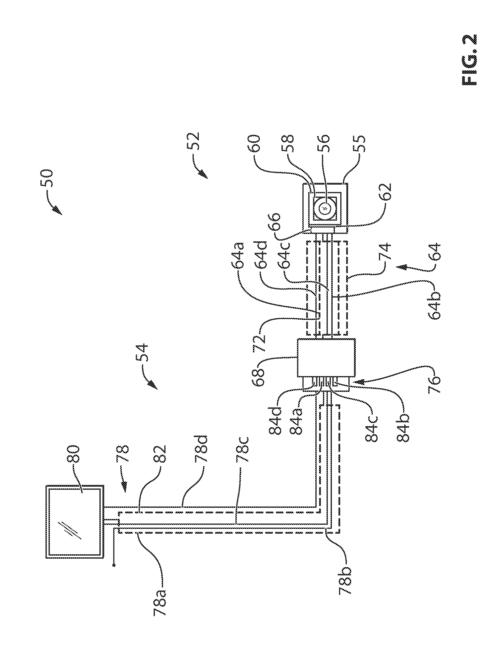
A camera assembly for a vehicle includes an end connector with a first connection point that carries a video+signal, a second connection point that carries power, and a third connection point that receives a video−signal, video shield current and ground current. The camera assembly may connect to a conduit assembly of the vehicle that includes a first conduit that carries the video+signal from the end connector to a display in the vehicle, a second conduit that carries power from a power source (such as a battery) to the camera assembly, and a third conduit that connects between the third connection point and a ground point for the display in the vehicle. The camera may include a radio frequency identification element operable to wirelessly communicate between a remote device and the camera to identify the camera module and / or to program the camera.

Description

CROSS REFERENCE TO RELATED APPLICATIONS[0001]The present application is a 371 national phase application of PCT Application No. PCT / US2011 / 059089, filed Nov. 3, 2011, which claims the priority benefit of U.S. provisional applications, Ser. No. 61 / 490,195, filed May 26, 2011, and Ser. No. 61 / 410,132, filed Nov. 4, 2010, which are hereby incorporated herein by reference in their entireties.FIELD OF THE INVENTION[0002]The present invention relates to vehicular camera systems, and more particularly to single ended, NTSC vehicular camera systems.BACKGROUND OF THE INVENTION[0003]Vehicular cameras typically include connectors with 6 pins that are used to connect to the rest of the vehicle. As a result, the connector directly impacts the size of the camera, the number of components in the camera, and the cost of the camera. Additionally, the wiring that extends from the connector to points in the vehicle such as a display in the instrument panel and a vehicle ground adds to the overall cost...

Claims


Application Information

Patent Timeline
Patent Type & Authority Patents(United States)
IPC IPC(8): H04N5/225H04N5/232H04N5/217
CPCH04N5/2252H04N5/217H04N5/2251H04N5/232H04B7/24H04N23/51H04N23/81H04N23/661H04N23/63H04N23/57H04N23/54H04N25/76
Inventor GEBAUER, DUANE W.BALLY, NAZAR F.HARRIS, BRETTSHRINER, RICHARD D.
Owner MAGNA ELECTRONICS INC
Learn More