
Wireless power control method, system, and apparatus utilizing a wakeup signal to prevent standby power consumption

a technology of wakeup signal and power control method, which is applied in the direction of transmission, transportation and packaging, circuit monitoring/indication, etc., can solve the problems of instantaneous discharge phenomenon and degradation of battery pack lifespan and performan

Active Publication Date: 2015-11-17
GE HYBRID TECH
View PDF62 Cites 16 Cited by
  • Summary
  • Abstract
  • Description
  • Claims
  • Application Information

AI Technical Summary

Benefits of technology

The invention is about a device that can transmit wireless power. The device has a control unit that can activate the power block to transmit power to a wireless power receiving device when a start signal is inputted through a user input unit. This means that the device can automatically activate the power block to transmit power as soon as the user presses the start button, making the power transmission process easier and more user-friendly.

Problems solved by technology

However, when the terminal supply method supplies electrical energy, since the terminal of the battery pack and the terminal of the charger have different potential differences, the terminal supply method may cause an instantaneous discharging phenomenon when the charger and the battery pack contact or separate from each other.
When foreign materials have accumulated in one or both terminals, the instantaneous discharge phenomenon may heat said materials, triggering a fire or the like.
Further, the electrical energy charged in the battery pack may be naturally discharged into the environment through the terminal of the battery pack, due to humidity or the like, which may lead to a degradation in lifespan and performance of the battery pack.

Method used


Image

  • Wireless power control method, system, and apparatus utilizing a wakeup signal to prevent standby power consumption
  • Wireless power control method, system, and apparatus utilizing a wakeup signal to prevent standby power consumption
  • Wireless power control method, system, and apparatus utilizing a wakeup signal to prevent standby power consumption

Examples


Embodiment Construction

[0030]Reference will now be made in detail to the present embodiments of the present invention, examples of which are illustrated in the accompanying drawings, wherein like reference numerals refer to the like elements throughout. The embodiments are described below in order to explain the present invention by referring to the figures.

[0031]According to embodiments of the present invention, a wireless power transmission system uses a near field wireless power transmission method, which may be but is not limited to electromagnetic induction or magnetic resonance. Other possible methods will be recognized by those skilled in the art.

[0032]The wireless power transmission system may be a resonant wireless power transmission system.

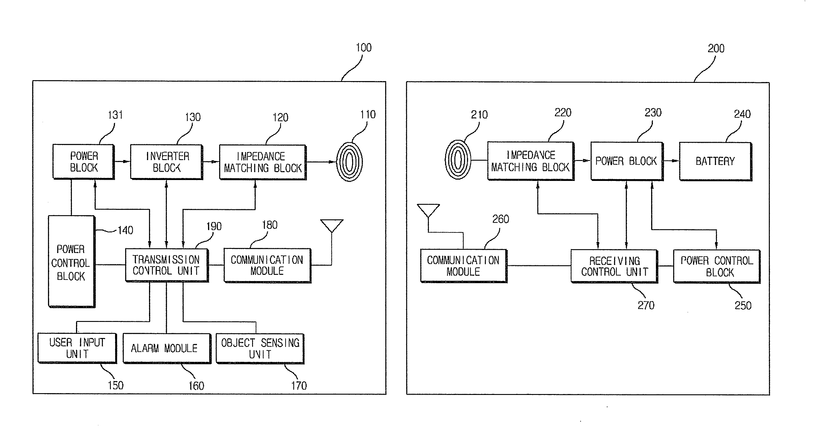
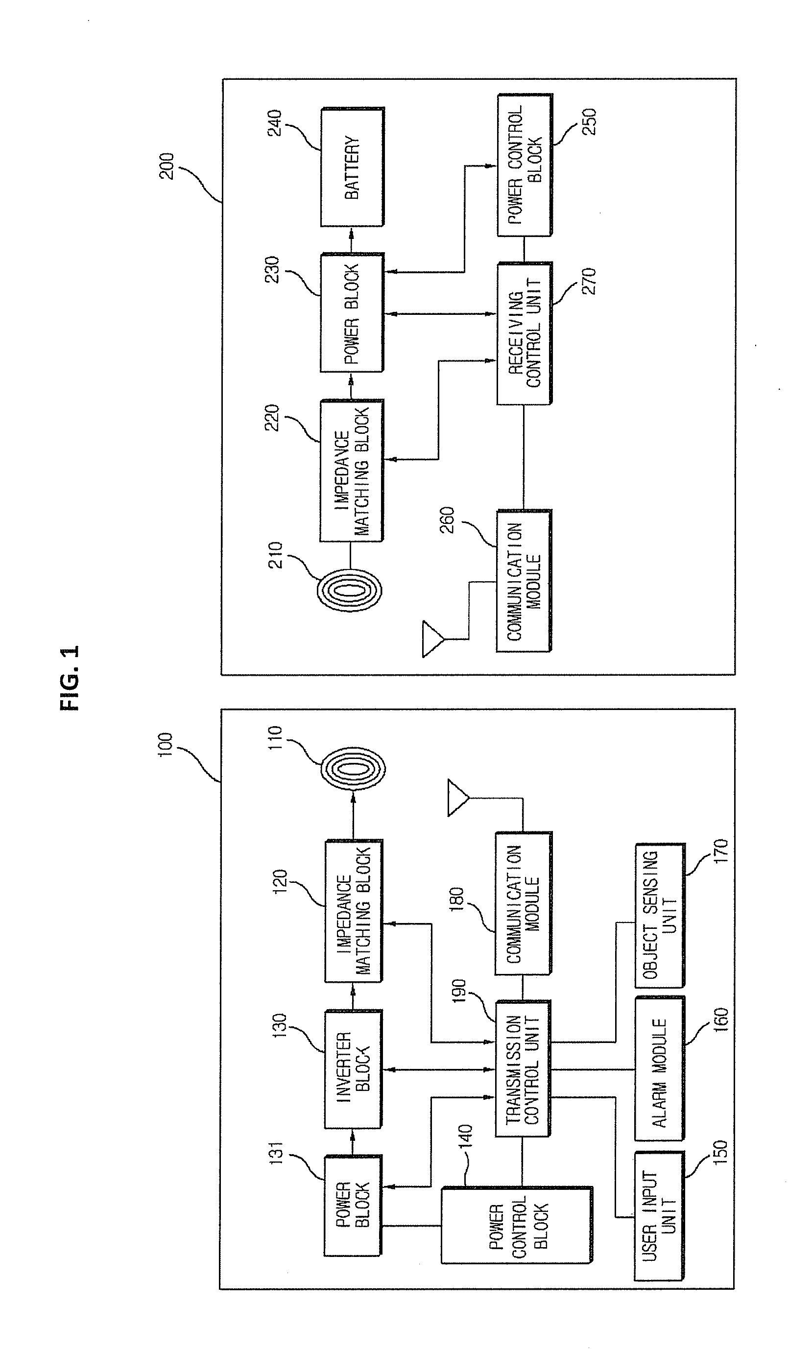
[0033]FIG. 1 is a block configuration diagram illustrating an electronic configuration of a wireless power transmission system, according to an embodiment of the present invention. According to the embodiment illustrated in FIG. 1, a wireless power transmissio...


PUM


Abstract

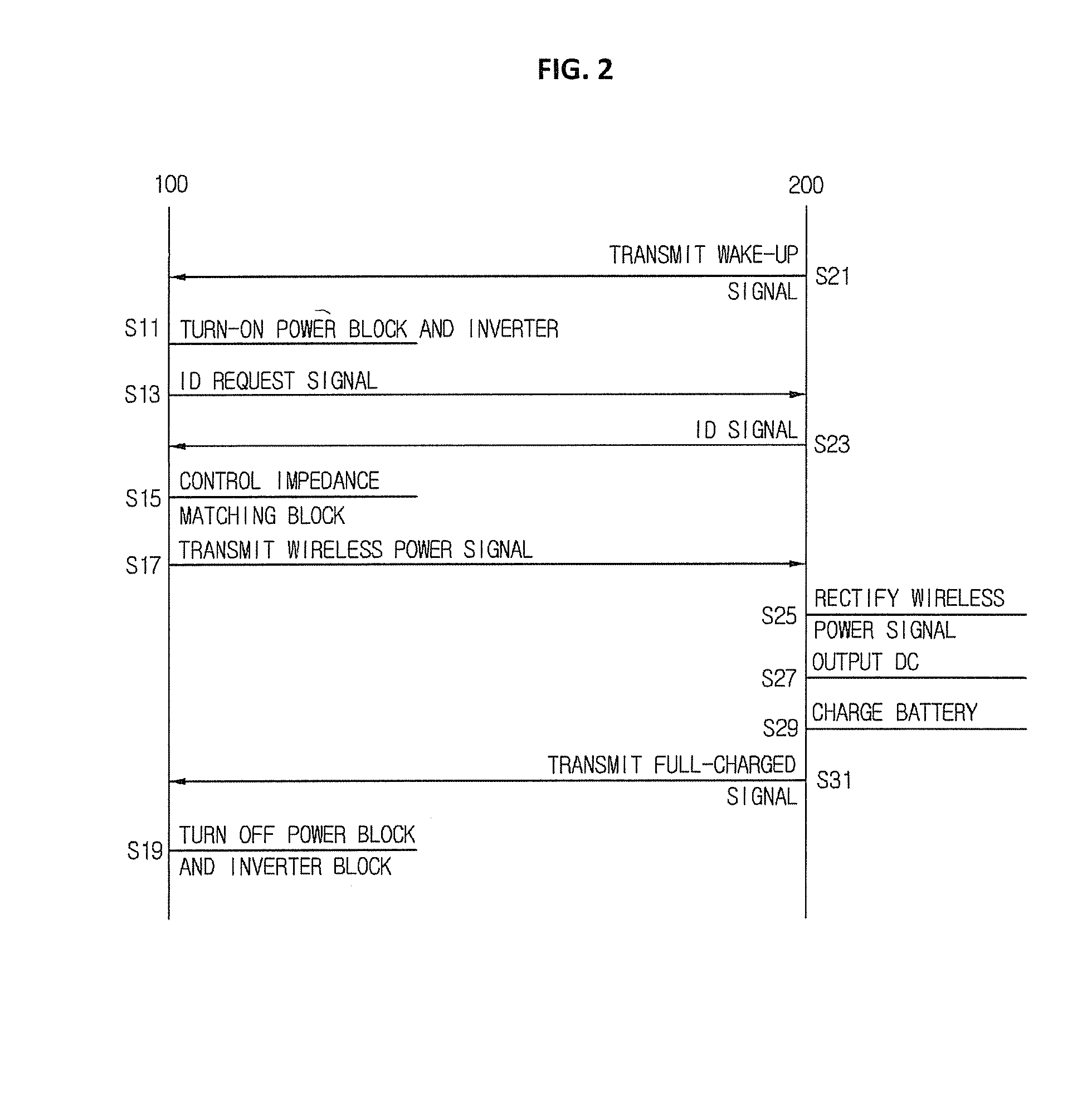
Disclosed herein are a wireless power transmission control method in a wireless power transmission system, including receiving awake-up signal from a wireless power receiving apparatus and transmitting a wireless power transmission signal to the wireless power receiving apparatus through a transmission coil of a wireless power transmission apparatus while activating a deactivated power block when the wake-up signal is received; a wireless power transmission apparatus using the same; and a wireless power receiving apparatus using the same.

Description

CROSS-REFERENCE TO RELATED APPLICATIONS[0001]This application claims the benefit of Korean Application No. 10-2012-0158114, filed Dec. 31, 2012, in the Korean Intellectual Property Office, the disclosure of which is incorporated in its entirety herein by reference.BACKGROUND OF THE INVENTION[0002]1. Field of the Invention[0003]The present invention relates to a wireless power transmission control method in a wireless power transmission system, a wireless power transmission apparatus using the same, and a wireless power receiving apparatus using the same.[0004]2. Description of the Related Art[0005]Generally, a battery pack is charged with electrical energy supplied from an external charger and supplies the charged energy to power the operation of portable terminals (mobile phones, PDAs, and the like). The battery pack generally comprises a battery cell which can be charged with electrical energy, a circuit for charging and discharging the battery cell (the discharging being to suppl...

Claims


Application Information

Patent Timeline
Patent Type & Authority Patents(United States)
IPC IPC(8): H02J7/00H04B5/00H02J7/02
CPCH04B5/0037H04B5/0093H02J7/025H02J2007/0049H04B5/266H04B5/79H02J7/0049H02J50/80H02J50/60H02J50/10H02J50/90H02J50/12
Inventor JUNG, CHUN-KILPARK, HEE-JEONGHWANG, BYONG-UK
Owner GE HYBRID TECH
Learn More