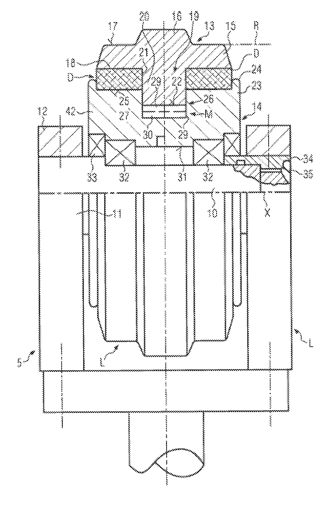
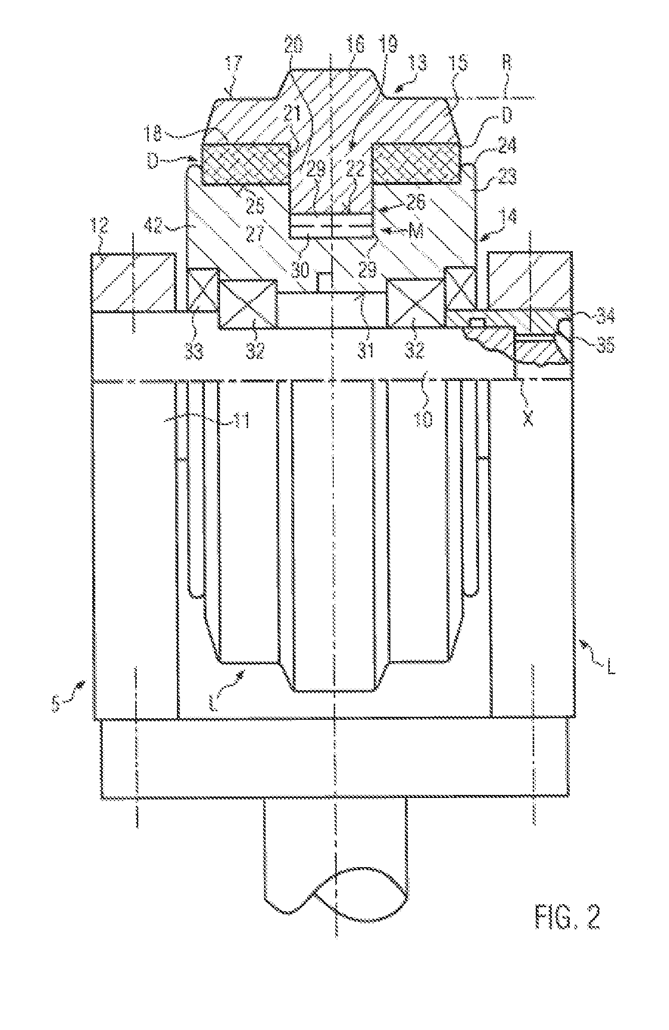
[0015]The set object is achieved with the features of the present invention in which the drive chain wheel and / or the idler wheel is, between the axle and the caterpillar track, divided into inner and outer annular parts which are guided relatively to the axle and are exclusively movably radially relative to one another and so as to slide against each other. The at least two damping layers are arranged internally between the parts. Here, the damping layers take on loads exerted by the caterpillar track on the metallic parts of the drive chain wheel or the idler wheel, without, however, coming into direct contact with the caterpillar track. In this manner, an effective inner damping is achieved by consuming the energy from the essentially radially acting impacts in the damping layer with radial relative motions between the parts. Since the parts are guided to exclusively slide radially relative to one another, no impacts are transmitted via the sliding guide, but lateral guiding forces are built up. Impacts inevitably exerted by the caterpillar track in the driving operation are thus dampened by the integrated damping layers, whereby above all operating noise and also wear are reduced. However, the integration of the damping layers should be designed such that there is nevertheless a metallic contact also at least between the drive chain wheel and the caterpillar track in order not to overload the damping layers or to wear them down prematurely, and mainly to transmit lateral guiding forces. Despite the damping layers minimizing the operating noise, with the invention, shearing forces in the damping layers are avoided by the exclusively radial sliding guide, which will increase service life and ensure a stable, directed running of the caterpillar track over the wheels.
[0016]In one suitable embodiment, in the idler wheel and / or optionally in the drive chain wheel, in addition two annular damping layers with approximately identical diameters are provided axially outside and separated by a space in the axial direction, and in the region of the space, the metallic external teeth of the drive chain wheel or the guide collar of the idler wheel are arranged, so that here, mainly load transmission takes place, while the additional damping layers dampen abrupt energy peaks from impacts generated by the caterpillar track without being overloaded in the process, because the inner damping layers are also effective. The respective additional damping layer is attached outside on the respective bearing shoulder e.g. at the idler wheel, and firmly connected to it, preferably by drawing up, oversize shrink fitting, spraying, gluing or vulcanizing. While the raised guide collar transmits at least lateral guiding forces optionally in direct contact with the caterpillar track, impacts of the caterpillar track are also dampened by the additional damping layers which do not have to transmit the total load of the caterpillar track as would be the case with a solid rubber jacket of the idler wheel. This solution can lead to a very silent operating noise especially with the idler wheel.
[0018]In a suitable embodiment, the outer part of the drive chain wheel comprising the circumferential teeth and embodied as single-part ring disk or as ring disk assembled from segments with an internal circumferential base part and at least one first radial guiding structure, the inner part, which is preferably separable for assembly, is embodied with a circumferential crown matching the base part with at least one second radial guiding structure matching the first radial guiding structure, cylindrical or conical support surfaces facing each other are provided at the base part and at the crown, the respective damping layer is arranged between the support surfaces, optionally firmly connected to a support surface, and the first and the second radial guiding structures engage each other with a radial free motion. This embodiment of the drive chain wheel is structurally simple and fail-safe with the radial sliding guide.
[0020]Suitably, the crown is axially wider than the base part or the supporting ring, annular flanges radially projecting to the outside are provided at the edges of the crown which secure the base part or the supporting ring, respectively, in the axial direction without metallic contact because their protrusion is preferably smaller than the radial thickness of the damping layer. This also increases the lateral stiffness of the damping layers.
[0025]In a structurally simple embodiment, the first radial guiding structure has an annular flange projecting from the adjacent support surface to the inside with an approximately rectangular cross-section, and the second radial guiding structure comprises an annular groove, also with an approximately rectangular cross-section, which is recessed to the inside with respect to the support surface. A reversed structural shape is also possible, i.e. an annular flange gripping from the inner part to the outside and an annular groove immersed in the outer part. The annular flange is stably radially guided in the annular groove over a large surface and relieves the damping layer from possibly damaging flexing and shearing forces. Here, there can be direct metallic contact, or the guiding surfaces can comprise sliding or protecting coverings.


