Input apparatus, control apparatus, control system, electronic apparatus, and control method
a control apparatus and input technology, applied in the field of input apparatus, control apparatus, control system, electronic apparatus, and control method, can solve the problems of poor operation feeling and poor operation feeling, and achieve the effect of improving the operation feeling of scrolling an imag
- Summary
- Abstract
- Description
- Claims
- Application Information
AI Technical Summary
Benefits of technology
Problems solved by technology
Method used
Image
Examples
first embodiment
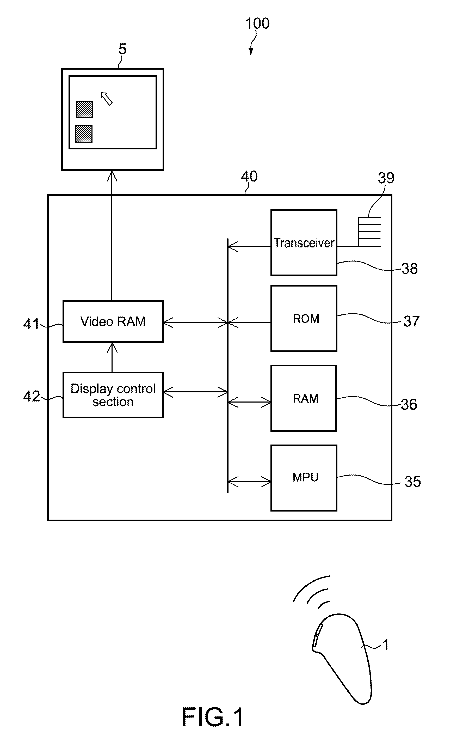
[0106]FIG. 1 is a diagram showing a control system according to a first embodiment of the present invention. A control system 100 includes a display apparatus 5, a control apparatus 40, and an input apparatus 1.
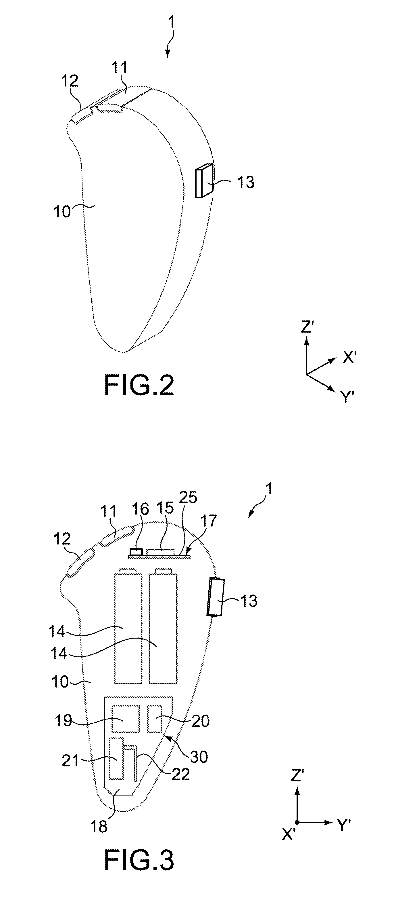
[0107]FIG. 2 is a perspective diagram showing the input apparatus 1. The input apparatus 1 is of a size that a user is capable of holding. The input apparatus 1 includes a casing 10. Further, the input apparatus 1 includes an operation section 23 (see FIG. 6) including a button 11 and a button 12 adjacent to the button 11 that are provided at a center of an upper portion of the casing 10, and a button 13 provided at a side portion of the casing 10.
[0108]Typically, the buttons 11, 12, and 13 are each a press-type button. The operation section 23 is not limited to the press-type button, and a bar-type operation section that is operated with one end as a fulcrum, or a slide-type operation section may also be used. Each of the buttons 11, 12, and 13 includes a built-in switch (no...
second embodiment
[0176]Next, a second embodiment of the present invention will be described. The first embodiment above has described a case where the scroll direction is biased in (restricted to) a uniaxial direction of one of the horizontal-axis direction and the vertical-axis direction on the screen 3. The second embodiment is different from the first embodiment in that the scroll direction is biased in (restricted to) biaxial directions of the horizontal-axis direction and the vertical-axis direction on the screen 3. Therefore, that point will mainly be described.
[0177]FIG. 12 is a flowchart showing an operation of the input apparatus 1 according to the second embodiment.
[0178]As shown in FIG. 12, in Steps 301 to 304, processes that are the same as those of Steps 201 to 204 of FIG. 10 are executed. In other words, when judged that the button 13 is not pressed (NO in Step 303), information on velocity values is transmitted from the input apparatus 1 (Step 304), and the pointer 2 displayed on the ...
third embodiment
[0189]Next, an input apparatus according to a third embodiment of the present invention will be described.
[0190]The third embodiment mainly describes points different from those of the second embodiment above.
[0191]FIG. 14 is a flowchart showing an operation of the input apparatus 1 according to the third embodiment.
[0192]As shown in FIG. 14, in Steps 401 to 404, processes that are the same as those of Steps 301 to 304 of FIG. 12 are executed. In this case, by the user operating the input apparatus 1 3-dimensionally in a state where the button 13 is not pressed, the pointer 2 moves on the screen 3 in accordance with the 3-dimensional operation.
[0193]When the button 13 is pressed, an operation signal is output from the switch provided to the button 13 and input to the MPU 19 (YES in Step 403). Upon being input with the operation signal, the MPU 19 calculates a tilt angle ξ of a combined vector of the first velocity value and the second velocity value using Equation (5) below (Step 40...
PUM
 Abstract
Description
Claims
Application Information
 - R&D
- Intellectual Property
- Life Sciences
- Materials
- Tech Scout
- Unparalleled Data Quality
- Higher Quality Content
- 60% Fewer Hallucinations
Browse by: Latest US Patents, China's latest patents, Technical Efficacy Thesaurus, Application Domain, Technology Topic, Popular Technical Reports.
© 2025 PatSnap. All rights reserved.Legal|Privacy policy|Modern Slavery Act Transparency Statement|Sitemap|About US| Contact US: help@patsnap.com


