
Mounting system for installing solar system modules on roofs

a solar system and module technology, applied in the field of roof hooks, can solve problems such as insufficient adjustment possibilities or lack of fixing, and achieve the effects of convenient mounting, fast and easy access to fastening elements, and convenient mounting

Active Publication Date: 2015-10-06
KIESELBACH SOLAR
View PDF21 Cites 6 Cited by
  • Summary
  • Abstract
  • Description
  • Claims
  • Application Information

AI Technical Summary

Benefits of technology

[0003]An advantage of the present invention is an improved roof hook which has easily reachable fastening elements and which enables faster and easier mounting.
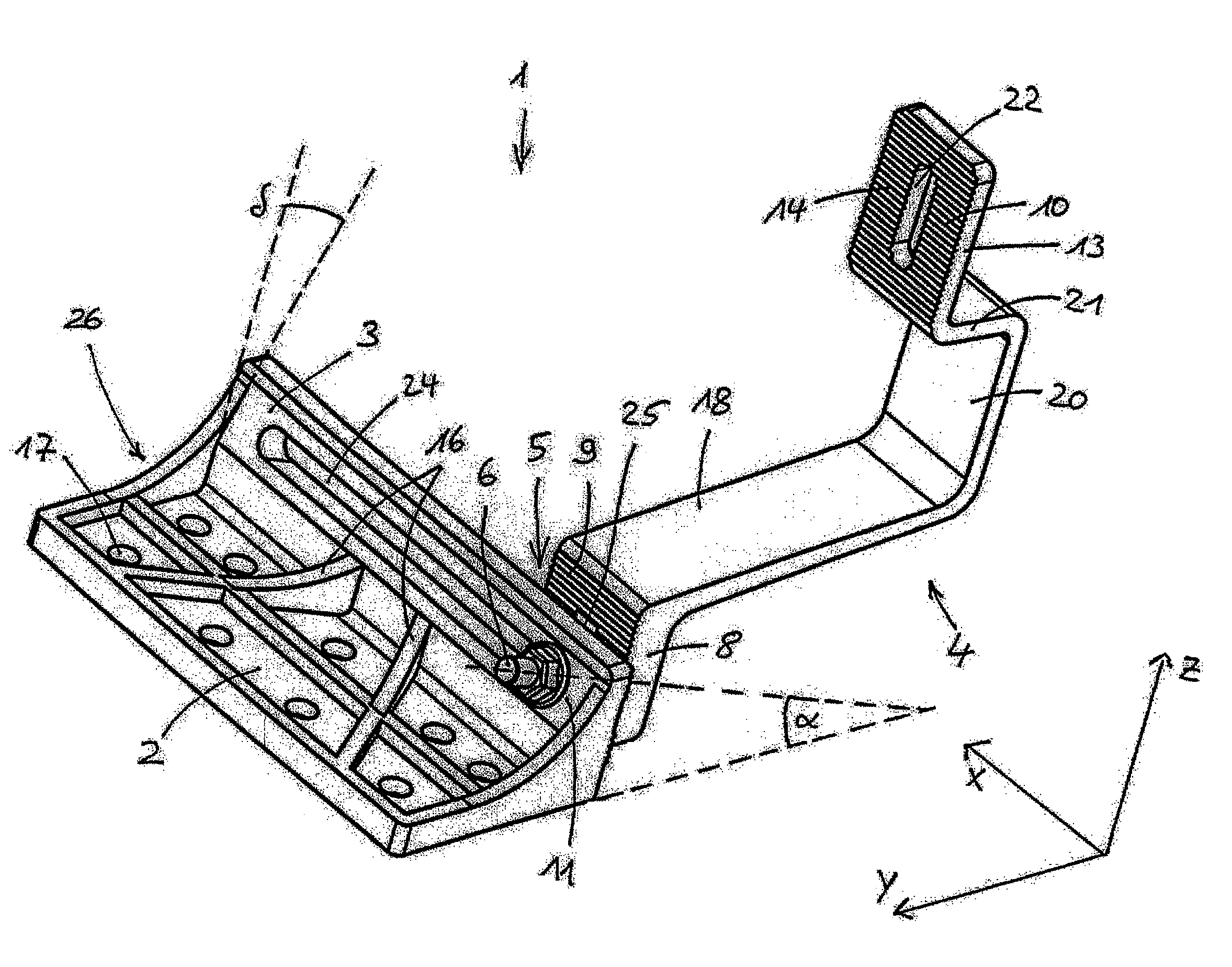
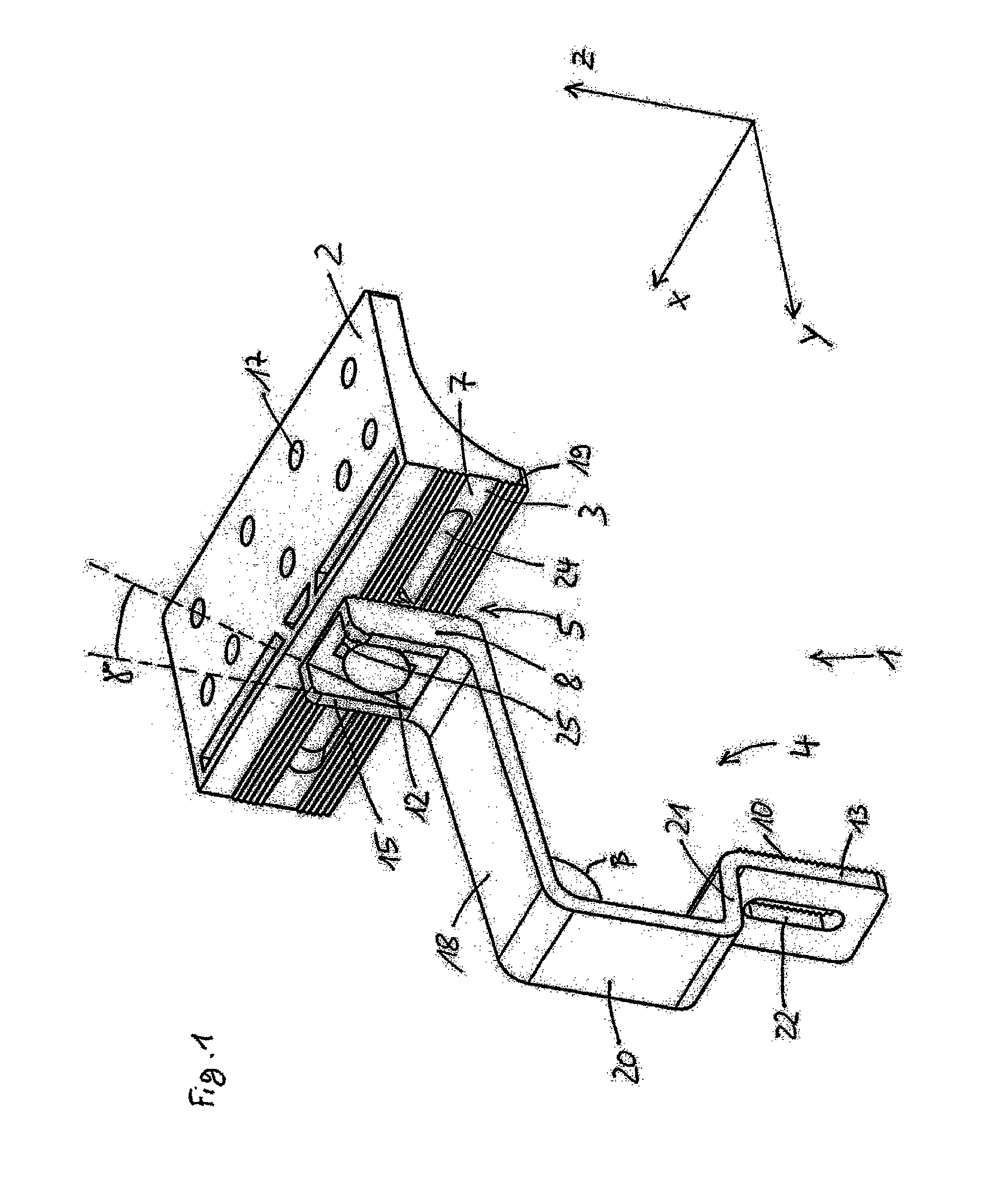
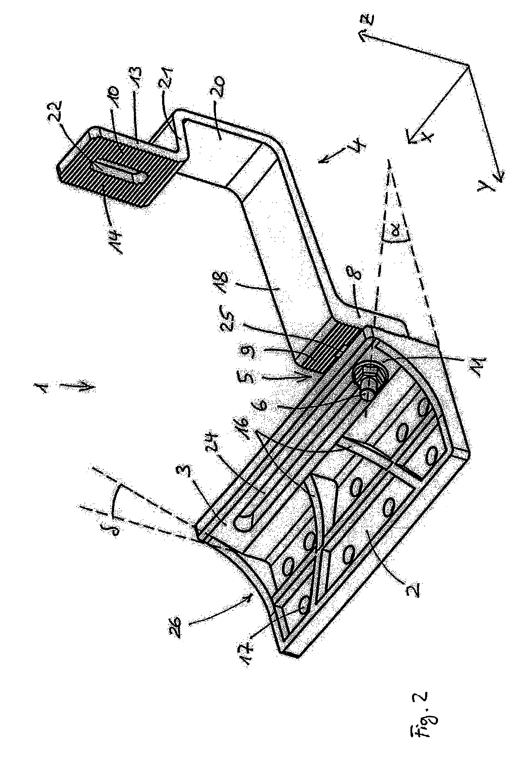
[0004]In accordance with the present invention, there is provided a roof hook for mounting solar installation modules on roofs. The roof hook is comprised of a first fastening section, which extends in the X and Y direction for fixing a roof hook, a hook-shaped mount for fixing the solar installation module or a fastening profile for solar installation modules and a second fastening section which runs perpendicular to the first fastening section in the Z direction from the latter. The mount is adjustable on the second fastening section in the Z direction, and fasteners act obliquely to the Z direction for fixing the mount on the fastening section.
[0005]Advantageous configurations of the invention are given in the dependent claims.
[0006]A roof hook according to the present invention can be produced modularly from at least two components. The fastening surfaces which are made integral on the respective component are connected by force-fit, especially positively by a connecting element to the mount. In contrast to known adjustable roof hooks, the roof hook as claimed in the invention can be set / adjusted via an individual, i.e., single, easily reachable connecting element and can be adapted appropriately to the pantiles, which greatly facilities the mounting of solar installation modules high up on roofs. In this way, it becomes possible as claimed in the invention to implement the most varied types of roof mounting systems with a uniform first component.
[0007]One important advantage is achieved in that the roof hook as claimed in the invention can be adjusted essentially perpendicular to the roof surface or to the first fastening section so that a location bordering the roof hook on the pantiles is not influenced, as would be the case for diagonal adjustability.
[0008]Another important advantage of the invention is that the fastening element which is provided for adjusting the mount in the vertical direction to the roof surface is not located parallel to the roof surface, i.e., orthogonally to the adjustment direction, but is tilted obliquely in the direction of the mount. In this way, the fastening element can be easily reached, which greatly facilitates mounting.

Problems solved by technology

The disadvantage in the known roof hooks is the involved mounting due to poorly reachable fastening elements and lacking or insufficient adjustment possibilities to the roof hooks on different pantiles and / or different solar installation modules or fastening profiles for solar installation modules.

Method used


Image

  • Mounting system for installing solar system modules on roofs
  • Mounting system for installing solar system modules on roofs
  • Mounting system for installing solar system modules on roofs

Examples


Embodiment Construction

[0028]In the figures the same components and components with the same action are identified with the same reference numbers.

[0029]The figures show a roof hook or mounting system 1. To simplify the description of the location of the individual components of the roof hook 1 to one another, a Cartesian coordinate system with three axes X, Y and Z which run orthogonally to one another is introduced.

[0030]The roof hook 1 as claimed in the invention has a base unit having a first fastening section 2 which is rectangular in a plan view with a fastening surface which extends in the X and Y direction. The first fastening section 2 is provided with two parallel rows of mounting holes 17 which run in the X direction. These holes are used to accommodate fastening screws (not shown) for fixing the roof hook 1 with its first fastening section 2 on the roof.

[0031]In addition to the first fastening section 2, the base unit of the roof hook 1 has a second fastening section 3 which is rectangular in ...


PUM


Abstract

A roof hook for mounting of solar installation modules on roofs. The roof hook has a first fastening section, which extends in the X and Y direction for fixing a roof hook, a hook-shaped mount for fixing the solar installation module or a fastening profile for solar installation modules and a second fastening section which runs perpendicular to the first fastening section in the Z direction from the latter. The mount is adjustable on the second fastening section in the Z direction, and fasteners act obliquely to the Z direction for fixing the mount on the fastening section.

Description

FIELD OF THE INVENTION[0001]The invention relates to a roof hook for mounting of solar installation modules on roofs.BACKGROUND OF THE INVENTION[0002]Known roof hooks in their fastening section have several bores for accommodating fastening screws. DE 20 2008 016 000 U1 shows a roof hook which is made divided and EP 0881339 A1 discloses a safety roof hook. By means of the fastening screws the roof hook is fastened on the roof, especially to roof panels which lie under the pantiles. The hook-shaped holder section protrudes under the pantiles on the roof top. The solar installation modules are fastened directly or indirectly via fastening profiles to the holding section, generally with fastening screws. The known roof hooks are usually made integral and are generally welded together from two segments, specifically the fastening section and the holding section. The disadvantage in the known roof hooks is the involved mounting due to poorly reachable fastening elements and lacking or in...

Claims


Application Information

Patent Timeline
Patent Type & Authority Patents(United States)
IPC IPC(8): E04G3/20F16M13/02F24J2/52F24J2/46
CPCF24J2/5245F16M13/02F24J2/5247F24J2/5264F24J2002/4656F24J2002/4661Y02B10/20Y02E10/47F24S25/61F24S25/613F24S25/70F24S2080/09F24S2025/6002
Inventor ESKEN, MANFRED
Owner KIESELBACH SOLAR
Learn More