
Method for monitoring a tamper protection and monitoring system for a field device having tamper protection

a monitoring system and field device technology, applied in information technology support systems, program control, instruments, etc., can solve the problem that the attacker cannot obtain access to sensitive data, and achieve the effect of simple and reliable monitoring, simple operation, and easy access

Active Publication Date: 2015-09-29
SIEMENS AG
View PDF13 Cites 119 Cited by
  • Summary
  • Abstract
  • Description
  • Claims
  • Application Information

AI Technical Summary

Benefits of technology

The patent text describes a way to monitor the tamper protection of a field device using a simple and cost-effective method. The monitoring system is flexible and can be used for multiple devices, providing security against physical manipulation. The tamper monitoring device also has an autonomous power supply, reducing the need for external power and increasing its fault tolerance in case of power failure. In summary, the patent offers a technical solution for protecting against tampering in the field device.

Problems solved by technology

If a change in the capacitance is found, an alarm may be triggered and a memory on the board that, for example, contains sensitive data, may be deleted so that an attacker cannot obtain access to the sensitive data.

Method used


Image

  • Method for monitoring a tamper protection and monitoring system for a field device having tamper protection
  • Method for monitoring a tamper protection and monitoring system for a field device having tamper protection
  • Method for monitoring a tamper protection and monitoring system for a field device having tamper protection

Examples


Embodiment Construction

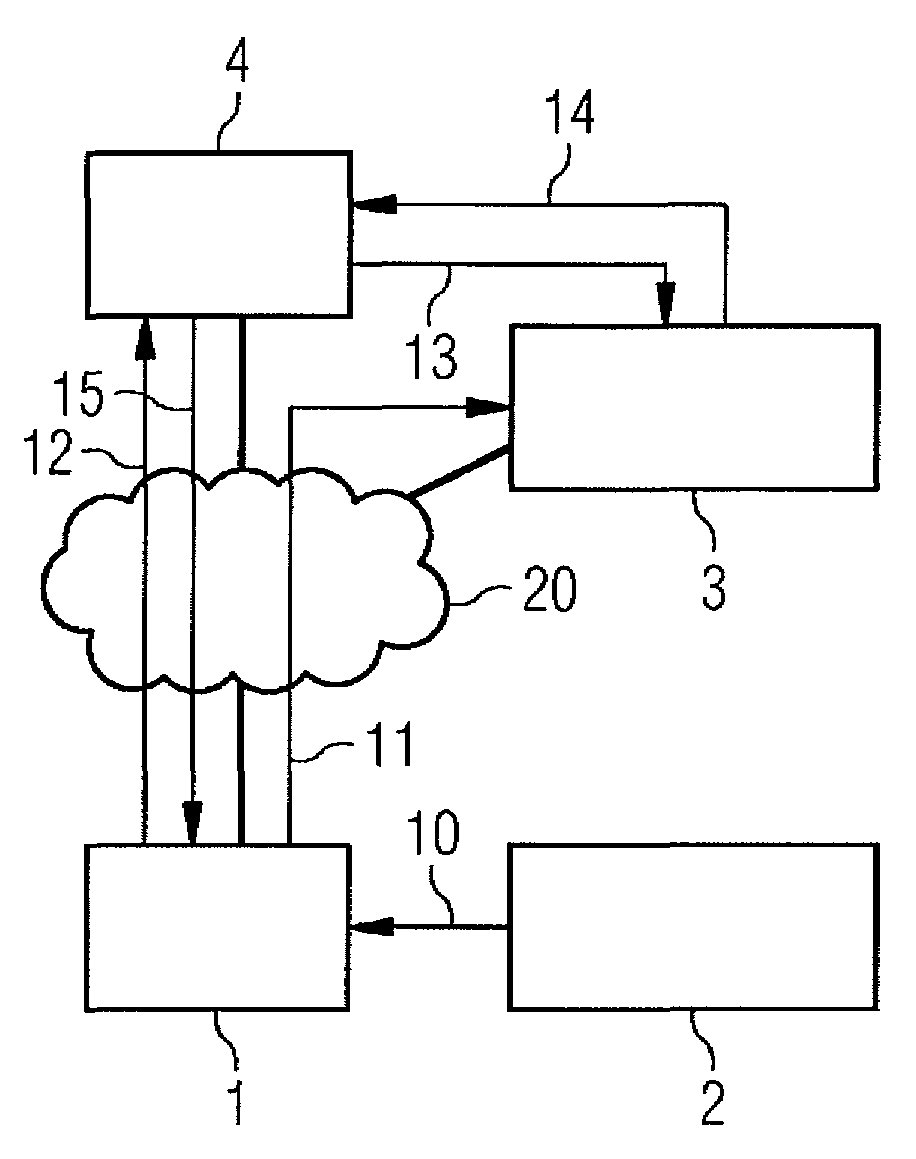
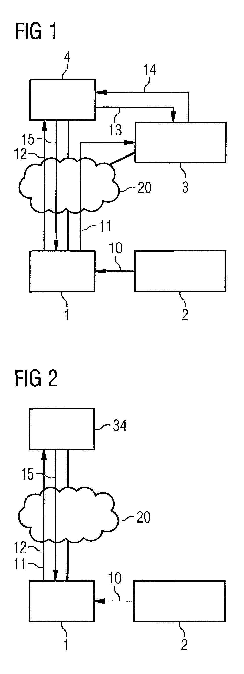
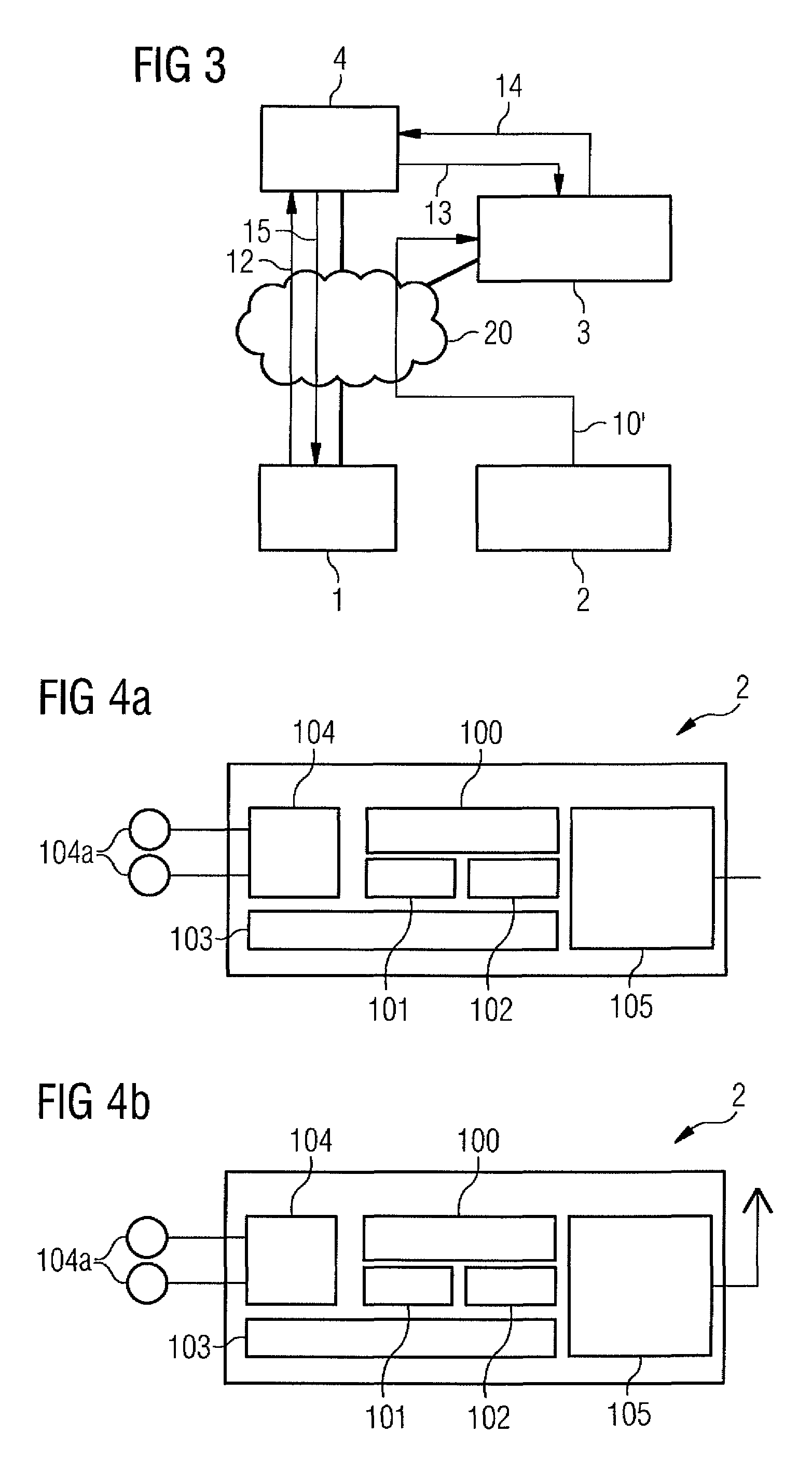
[0026]FIG. 1 depicts one embodiment of a monitoring system for a field device having tamper protection. In FIG. 1, reference symbol 1 designates a field device. The field device 1 is connected to a tamper monitoring device 2. The tamper monitoring device 2 is configured to monitor the field device 1 with respect to whether the field device 1 is manipulated physically. The field device 1 is also connected to a registration device 3 for registering and status monitoring of the field device 1. The registration device 3, in turn, exchanges data with a monitoring device 4 for controlling and monitoring the field device 1. The monitoring device 4 is connected to the field device 1 via the Internet 20 according to FIG. 1.

[0027]If the tamper monitoring device 2 has not detected any physical manipulation or a tamper event, the tamper monitoring device 2 issues a non-manipulation certificate or a non-tampering assertion “NTA” and transmits the non-manipulation certificate or NTA (reference sy...


PUM


Abstract

The embodiments relate to tamper protection of a field device. The method includes: checking whether manipulation of the field device has taken place; outputting a non-manipulation certificate in case a negative inspection result is determined; transferring the non-manipulation certificate; a registration device checking the non-manipulation certificate; determining an active status of the field device in case the non-manipulation certificate is valid; checking the field device by querying the status of the field device; transferring field device data to the monitoring device; and accepting the field device data if the field device has an active status. The invention further relates to a monitoring system for a field device and a use.

Description

[0001]The present patent document is a §371 nationalization of PCT Application Serial Number PCT / EP2012 / 056517, filed Apr. 11, 2012, designating the United States, which is hereby incorporated by reference, and this patent document also claims the benefit of DE 10 2011 007 572.0, filed Apr. 18, 2011, which is also hereby incorporated by reference.FIELD[0002]The present embodiments relate to tamper protection, a monitoring system for a field device having tamper protection, and a method for using a monitoring system.BACKGROUND[0003]Field devices, for example traffic signal installations for traffic control, signal installations for trains, and switches, are usually connected to a control station or a signal box for the operating and monitoring thereof. In this context, the communication between field device and control station may take place both by wired connections (run cables) or also wirelessly by a radio link.[0004]In order to be able to detect a physical manipulation at a field...

Claims


Application Information

Patent Timeline
IPC IPC(8): G06F21/86G05B19/042
CPCG06F21/86G05B19/0425G05B2219/37038Y04S40/20
Inventor FALK, RAINERFRIES, STEFFEN
Owner SIEMENS AG
Learn More