
Control system for autonomous operation

a control system and autonomous technology, applied in the direction of electric programme control, program control, instruments, etc., can solve the problem of more complex automation system

Active Publication Date: 2015-09-29
SYDNEY THE UNIV OF +1
View PDF49 Cites 16 Cited by
  • Summary
  • Abstract
  • Description
  • Claims
  • Application Information

AI Technical Summary

Benefits of technology

This solution enables more extensive automation and improved safety by allowing for precise control and management of autonomous operations within defined zones, enhancing the integration of autonomous systems and reducing the complexity of managing diverse equipment and personnel in mining operations.

Problems solved by technology

As the complexity of the processes or machinery increases, the more complex the automation system becomes.

Method used


Image

  • Control system for autonomous operation
  • Control system for autonomous operation
  • Control system for autonomous operation

Examples


Embodiment Construction

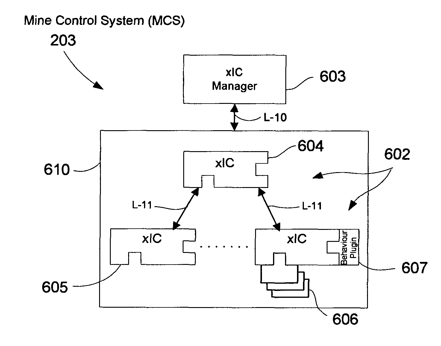
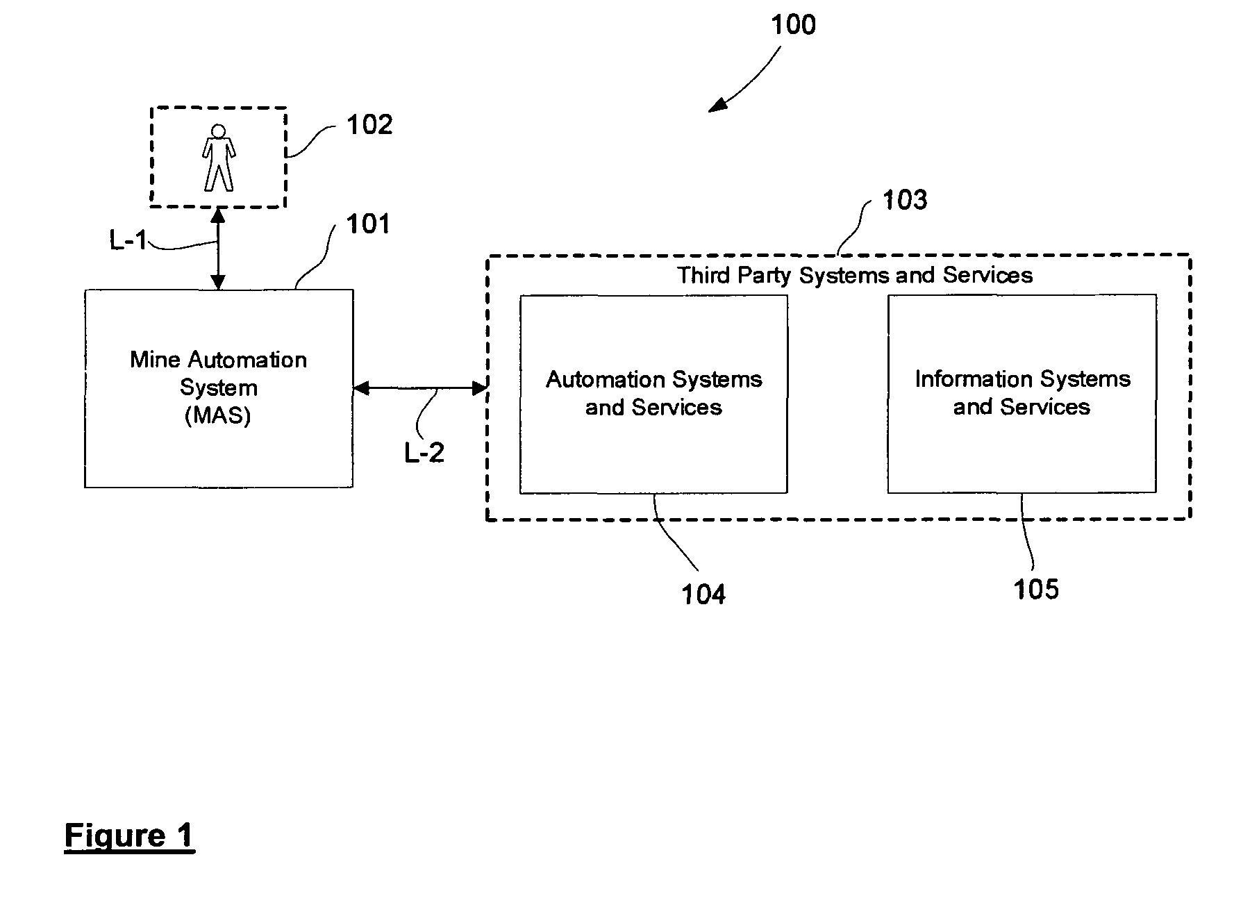
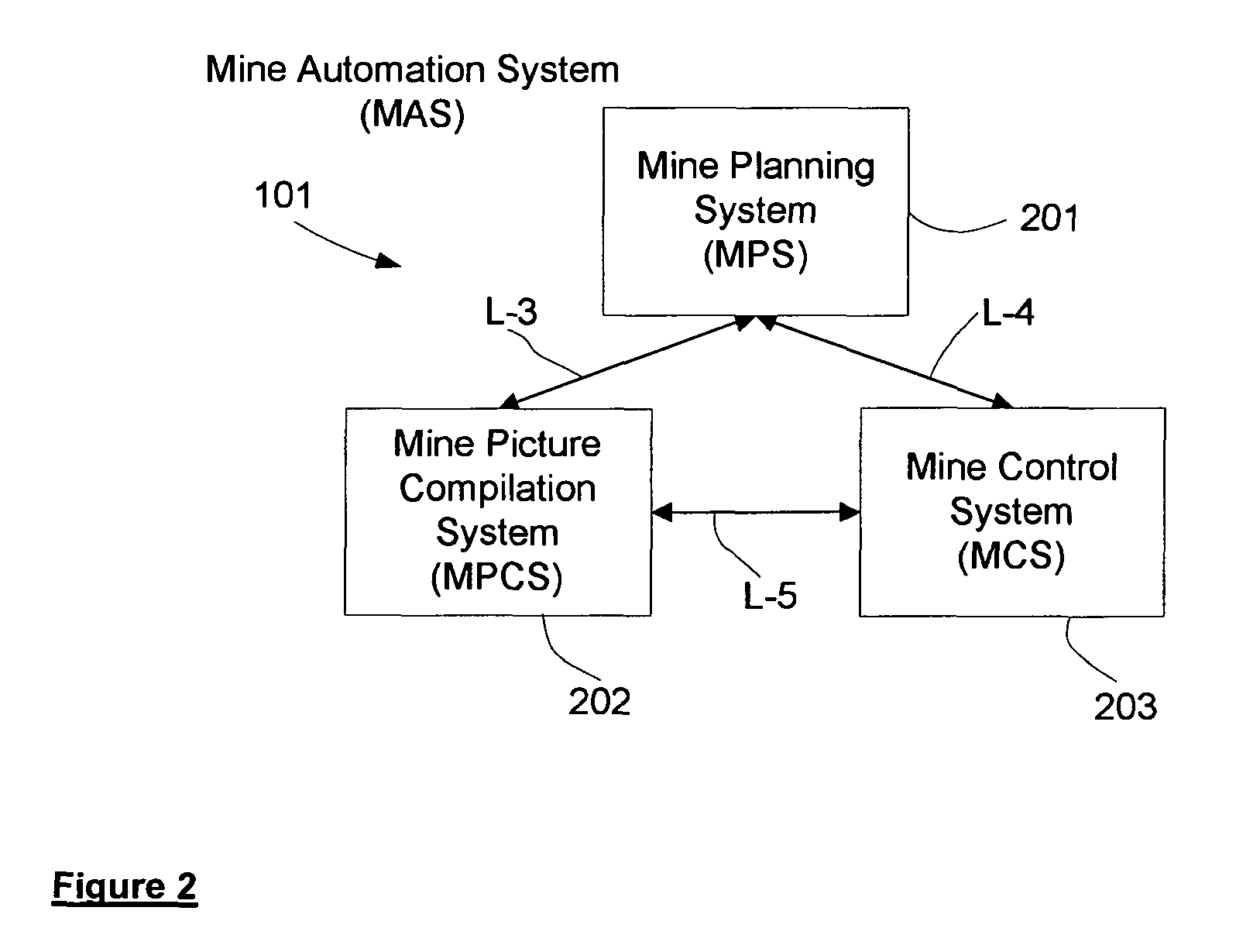
[0039]Broadly defined, the systems and methods described below enable autonomous operations to be effected within a defined geographical region. A plurality of localised zones having operation-defined geographical boundaries are established within the region and autonomous operating systems perform specific autonomous operations within the localised zones, the autonomous operating systems controlling one or more autonomous entities, for example self-guided and operated vehicles. An autonomous system of a management party may be integrated with the autonomous operating systems. An operator may (but need not necessarily) also be enabled to exercise overriding control over the management party autonomous system and, by way of that system, over the autonomous operating systems.

[0040]The expression “operation-defined geographical boundaries” is to be understood as meaning boundaries that embrace zones in which operations are conducted or in which operations may from time to time be condu...


PUM


Abstract

A hierarchical control system (203) for supervising operations of an autonomous operator located within a defined geographical region containing a localized zone having an operation-defined boundary. The control system (203) has a primary controller (604) associated with the defined geographical region and a secondary controller (605) associated with the localized zone. The secondary controller (605) is responsive to the supervisory control of the primary controller (604). The autonomous operator, if located within the localized zone, is responsive to the supervisory control of the secondary controller (605).

Description

CROSS-REFERENCE TO RELATED APPLICATIONS[0001]This patent application is a U.S. National Phase application under 35 U.S.C. §371 of International Application No. PCT / AU2010 / 000496, filed Apr. 30, 2010, entitled CONTROL SYSTEM FOR AUTONONOMOUS OPERATION, which claims priori to Australian patent application number 2009901933, Filed May 1, 2009.FIELD OF THE INVENTION[0002]This invention relates to the conducting of integrated operations within a defined geographical region and, in particular, to operations involving autonomous equipment. The invention has various applications and, in one of its possible embodiments, has application to a mine automation systemBACKGROUND OF THE INVENTION[0003]There is an increasing use of control systems to automate industrial processes or machinery, as automation may provide greater efficiency and safety. As the complexity of the processes or machinery increases, the more complex the automation system becomes. This is particularly so where autonomous oper...

Claims


Application Information

Patent Timeline
Patent Type & Authority Patents(United States)
IPC IPC(8): G05B23/02G05B19/414E21C41/26
CPCG05B19/4148E21C41/26G05B2219/33342
Inventor NETTLETON, ERICHENNESSY, ROSSDURRANT-WHYTE, HUGHGOKTOGAN, ALI HAYDARSINGH, SURYA P N
Owner SYDNEY THE UNIV OF
Learn More