Communication device, communication control method, and communication system
a communication control and communication device technology, applied in the direction of digital transmission, wireless communication services, machine-to-machine/machine-type communication services, etc., can solve problems such as traffic congestion, communication failure or deterioration of service quality, and achieve the effect of avoiding traffic congestion or reducing congestion
- Summary
- Abstract
- Description
- Claims
- Application Information
AI Technical Summary
Benefits of technology
Problems solved by technology
Method used
Image
Examples
first embodiment
[0075]
[0076][1-1. Outline of System]
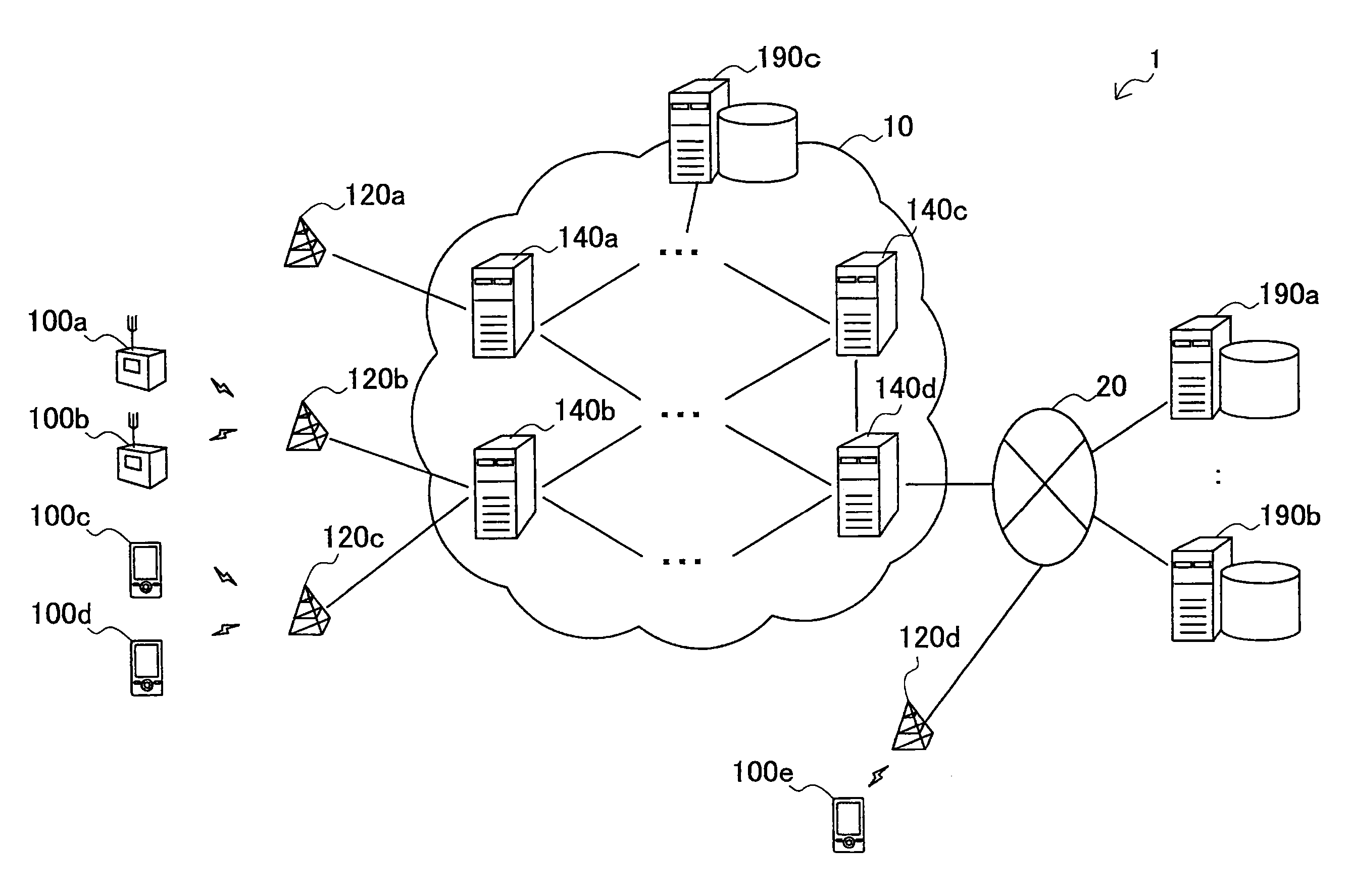
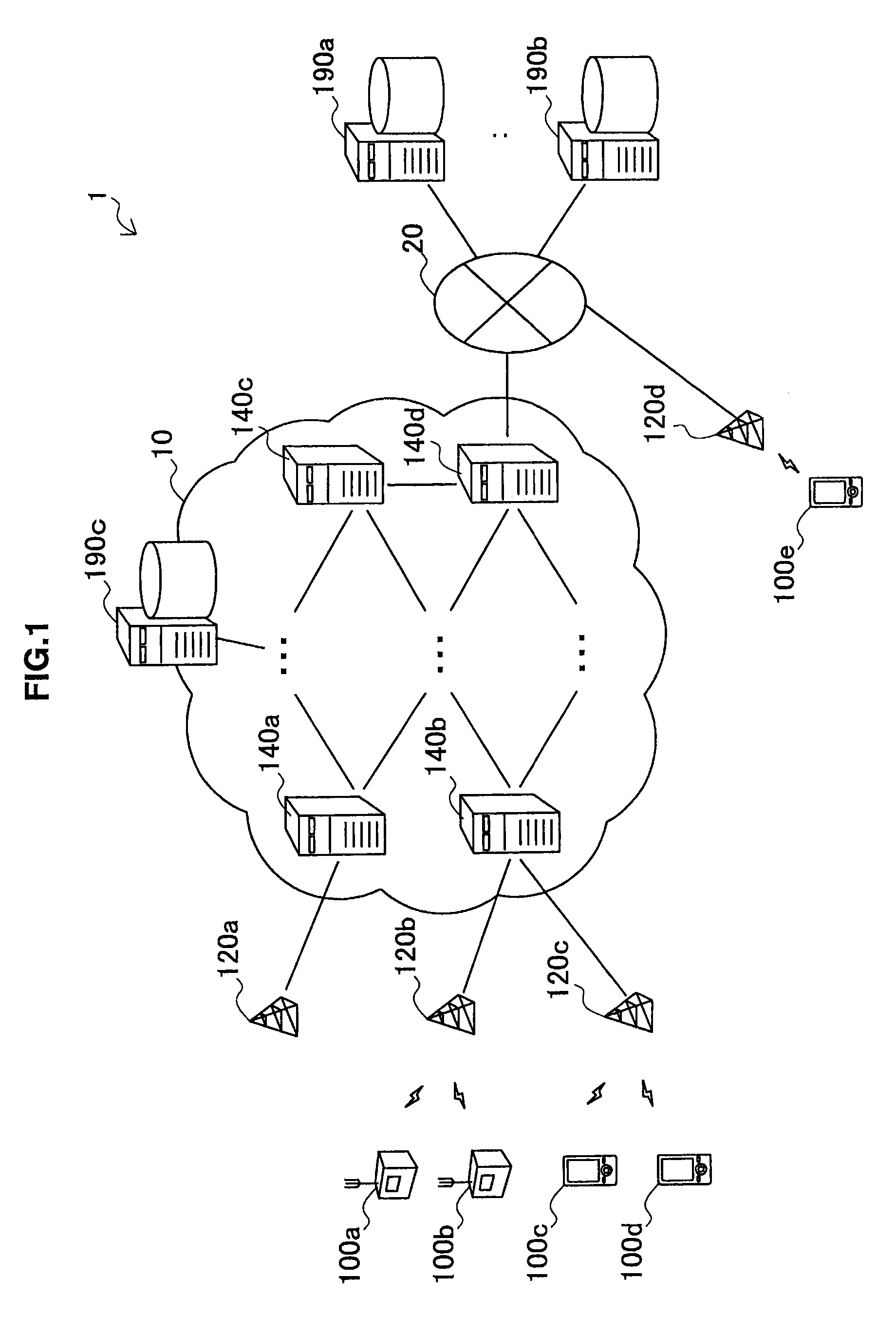
[0077]First, the first embodiment will be described using FIGS. 1 to 9. FIG. 1 is a schematic diagram illustrating an outline of a communication system 1 in accordance with the first embodiment. Referring to FIG. 1, the communication system 1 includes a plurality of terminal devices 100a to 100e, a plurality of base stations 120a to 120d, a plurality of communication devices 140a to 140d, and a plurality of application (AP) servers 190a to 190c. The plurality of communication devices 140a to 140d form a core network 10 in the communication system 1. The base station 120d and the AP servers 190a and 190b are connected to a network 20.
[0078]In this specification, when it is not necessary to distinguish the terminal devices 100a to 100e from one another, they are collectively referred to as a terminal device 100. The same is also true for a base station 120 (120a to 120d), a communication device 140 (140a to 140d), and an AP server 190 (190a to 190c)...
second embodiment
[0131]All the communication devices 140 within the core network 10 may not have a function serving as a forwarding destination node described here. In addition, content of forwarding destination node data may differ for every communication device 140 that functions as the forwarding destination node. That is, a first forwarding destination node may have forwarding destination data illustrated in FIG. 8A, while a second forwarding destination node may have forwarding destination data illustrated in FIG. 8B. The forwarding destination node data may be separately registered and updated in each forwarding destination node or may be collectively managed and dynamically updated in an information management server as described in the
[0132](2) Flow of Data Forwarding Process
[0133]FIG. 9 is a flowchart illustrating an example of the data forwarding process by the communication device 140 in accordance with this embodiment.
[0134]Referring to FIG. 9, first, the reception unit 142 of the commun...
application example
[0143][1-6. Application Example]
[0144]In the first embodiment, an example in which a forwarding destination of a data packet transmitted from an MTC terminal is mainly distributed among a plurality of forwarding destination node candidates has been described. However, a mechanism of selection of the above-described forwarding destination node is also applicable to a data packet transmitted to the MTC terminal. For example, the communication device 140 illustrated in FIG. 1 has additional forwarding destination data describing a plurality of forwarding destination node candidates for a data packet transmitted to the terminal device 100, and traffic is distributed based on control information within the data packet and the additional forwarding destination data, so that the forwarding destination node of the data packet transmitted to the terminal device 100 may be selected from the plurality of forwarding destination node candidates.
[0145]
[0146]Next, the second embodiment will be des...
PUM
 Abstract
Description
Claims
Application Information
 - R&D
- Intellectual Property
- Life Sciences
- Materials
- Tech Scout
- Unparalleled Data Quality
- Higher Quality Content
- 60% Fewer Hallucinations
Browse by: Latest US Patents, China's latest patents, Technical Efficacy Thesaurus, Application Domain, Technology Topic, Popular Technical Reports.
© 2025 PatSnap. All rights reserved.Legal|Privacy policy|Modern Slavery Act Transparency Statement|Sitemap|About US| Contact US: help@patsnap.com


