Hand puller with rope reel

a rope reel and hand puller technology, applied in the field of hand pullers, can solve problems such as limiting usag

Inactive Publication Date: 2015-08-25
WIN CHANCE METAL
View PDF18 Cites 1 Cited by
  • Summary
  • Abstract
  • Description
  • Claims
  • Application Information

AI Technical Summary

Benefits of technology

[0008]Another objective of the present invention is to provide a hand puller with a rope reel in which a reel is moveably coupled with the body, so that two driven gears of the reel mesh with two driving gears of the body. Hence, the body is rotated to roll the chain or the steel cable effectively.

Problems solved by technology

When desiring to pull the goods more strongly, another hand puller is applied to pull a chain or a steel cable, thus limiting usage.

Method used


Image

  • Hand puller with rope reel
  • Hand puller with rope reel
  • Hand puller with rope reel

Examples


first embodiment

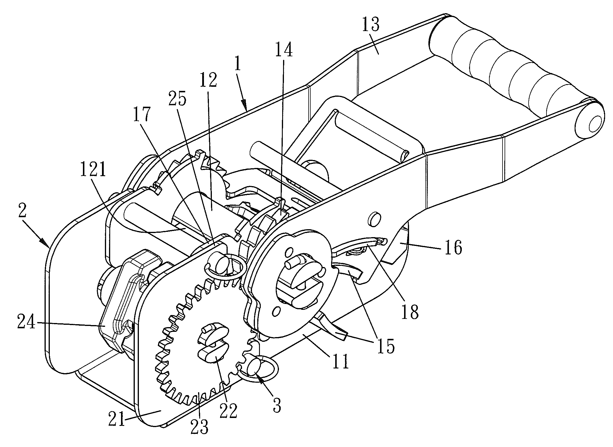
[0028]With reference to FIGS. 3-7, a hand puller with a rope reel according to the present invention comprises: a body 1 and a reel 2. The body 1 includes a fixing holder 11, a first rotary shaft 12 inserted into the fixing holder 11, a rotating handle 13 pivoted with the fixing holder 11, two ratchet wheels 14 mounted on two ends of the first rotary shaft 12 outside the fixing holder 11, two stopping pieces 15 disposed on the fixing holder 11, a positioning post 16 for connecting with a locking unit, and a first connecting portion 17 with plural holes 171. Thus, when the two stopping pieces 15 are pushed to retain with the two ratchet wheels 14, thus generating a single-direction stopping function. The rotating handle 13 has a pushing plate 18 retained with the two ratchet wheels 14 by rotating the rotating handle 13 to rotate the two ratchet wheels 14 and the first rotary shaft 12. The first rotary shaft 12 has a through orifice 121 defined thereon to insert and roll a rope. The f...

second embodiment

[0032]With reference to FIGS. 9-13, a hand puller with a rope reel according to the present invention comprises: a seat 21, a second rotary shaft 22 inserted through the seat 21, two driving gears 19 fixed on two ends of the first rotary shaft 12, two driven gears 23 secured on two ends of the second rotary shaft 22 and meshing with the two driving gears 19, and a steel cable roller 24′ mounted on the second rotary shaft 22 inside the seat 21. The seat 21 has a second connecting portion 25 disposed thereon and has a plurality of apertures 251 defined on the second connecting portion 25.

[0033]In use, the second connecting portion 25 of the reel 2 is aligned and overlapped with the first connecting portion 17 of the body 1, and at least one pin 3 is inserted into at least one of the plural holes 171 of the first connecting portion 17 and the plurality of apertures 251 of the second connecting portion 25. Thereafter, the reel 2 is movably coupled with the body 1. The two driven gears 2...


PUM

PropertyMeasurementUnit
flexibilityaaaaaaaaaa
tensile strengthaaaaaaaaaa

Abstract

A hand puller with a rope reel contains a body and a reel. The body includes a fixing holder, a first rotary shaft, a rotating handle, two ratchet wheels, and at least one stopping piece. The rotating handle having a pushing plate, and the first rotary shaft has two driving gears. The reel includes a seat, a second rotary shaft, two driven gears, and a chain roller. The body includes a first connecting portion with plural holes, and the seat has a second connecting portion and a plurality of apertures. The reel and the body are movably coupled together, and the second connecting portion of the reel is aligned and overlapped with the first connecting portion of the body. At least one pin is inserted into at least one of the plural holes of the first connecting portion and the plurality of apertures of the second connecting portion.

Description

BACKGROUND OF THE INVENTION[0001]1. Field of the Invention[0002]The present invention relates to a hand puller and, more particularly, to a reel for a hand puller to roll a chain or a steel cable.[0003]2. Description of the Prior Art[0004]With reference to FIGS. 1 and 2, a conventional hand puller contains a fixing holder 10, a rotating handle 20, and a shaft 30 pivoted between the fixing holder 10 and the rotating handle 20. Two ends of the shaft 30 are fitted through two ratchet wheels 40. The fixing holder 10 has two stopping pieces 101 retained with the two ratchet wheels 40 to generate a single direction stopping function and has a positioning post 102 for inserting a short rope 50. The rotating handle 20 has a pushing plate 201 mounted thereon and retained with the two ratchet wheels 40 to drive the two ratchet wheels 40 and the shaft 30 to rotate. The shaft 30 has a through hole 301 defined thereon to insert a long rope 60. In use, the rotating handle 20 is rotated relative t...

Claims


Application Information

Patent Timeline
Patent Type & Authority Patents(United States)
IPC IPC(8): B21F9/00B66F3/00B60P7/08
CPCB60P7/0846B60P7/083Y10T24/2109
Inventor CHANG, WEN CHENG
Owner WIN CHANCE METAL
Why Eureka
Try Eureka