Liquid crystal device and electronic apparatus

a liquid crystal display device and electronic equipment technology, applied in static indicating devices, instruments, non-linear optics, etc., can solve the problems of inferior horizontal electric field mode liquid crystal display devices to the vertical electric field mode liquid crystal display devices, and it is more difficult to discriminate the image viewed in the oblique direction, so as to achieve effective lower image contrast and reduce image contrast

Inactive Publication Date: 2015-08-04
JAPAN DISPLAY INC
View PDF18 Cites 5 Cited by
  • Summary
  • Abstract
  • Description
  • Claims
  • Application Information

AI Technical Summary

Benefits of technology

[0012]An advantage of some aspects of the invention is that it provides a horizontal electric field mode liquid crystal display device capable of lowering contrast of an image when a display screen is viewed in a direction oblique to a normal direction thereof at a display mode of a narrow viewing angle by optimizing a driving voltage of viewing-angle control pixels relative to display pixels, and an electronic apparatus having the same.
[0016]In this case, by making a voltage applied between the pair of electrodes in the viewing-angle control pixel region at the time of driving the liquid crystal layer in the viewing-angle control pixel region higher than a voltage applied between the pair of electrodes in the display pixel region, for example, brightness of when the display screen is viewed from the oblique direction to the normal direction is varied. Therefore, it is possible to lower contrast of the image viewed from the oblique direction. As a result, it is possible to make it more difficult to discriminate the image viewed from the oblique direction.
[0018]In the liquid crystal device according to this aspect of the invention, preferably, one electrode of the pair of electrodes in the viewing-angle control pixel region is directly connected to a line supplied with a control signal (for example, ON or OFF signal). In this case, preferably, the one electrode in the viewing-angle control pixel region is connected to a viewing-angle control line driving circuit through the line. The viewing-angle control line driving circuit is configured to include a switching element such as transistor capable of switching electric signals (ON / OFF). The viewing-angle control line driving circuit supplies the control signal (for example, ON or OFF signal) to the one electrode of the pair of electrodes in the viewing-angle control pixel region, for example, by turning the switching element ON / OFF. In addition, the circuit supplies a signal corresponding toga predetermined reference electric potential to the other electrode in the viewing-angle control pixel region. By adopting such a configuration, it is possible to easily and efficiently apply a high voltage (viewing-angle control signal) to the one electrode in the viewing-angle control pixel region without applying a load to a driver IC for driving the liquid crystal layer and the like. As a result, the narrow viewing-angle display mode can be realized without difficulty by supplying one electrode in the viewing-angle control pixel region with a high voltage, for example, the control signal (ON signal) corresponding to the range of 10 to 15V.
[0020]By adopting such a configuration, for example, the viewing-angle control line driving circuit is capable of supplying an ON signal to an arbitrary viewing-angle control pixel region among a plurality of viewing-angle control pixel regions and simultaneously capable of supplying an OFF signal to another viewing-angle control pixel region different from the arbitrary viewing-angle control pixel region. Accordingly, by dividing a display screen (the planar region) into a plurality of display region (for example, two display regions), different viewing-angle controls (that is, narrow viewing-angle control and wide viewing-angle control) are performed on the divided display regions, respectively. For example, by applying the liquid crystal device having the configuration to a display apparatus such as a navigation system mounted on a vehicle, a map for guiding a user's destination and the like and an image (TV program, movie, or the like) different from the map can be displayed on the display screen (dual picture display). In this case, the viewing-angle control pixels for the display region on which the map is displayed is supplied with a control signal as an OFF signal from the viewing-angle control line driving circuit through the line, and simultaneously the viewing-angle control pixels for the display region on which the image different from the map is displayed is supplied with a control signal as an ON signal from the viewing-angle control line driving circuit through the line. By adopting such a configuration, only the map can be allowed to be visible for a driver sitting on a driver's seat which is positioned obliquely to a display screen such as a navigation system, and thus it is possible to secure driving safety. On the other hand, both of the map and the image may be allowed to be visible for a passenger sitting on the back seat, which is positioned in front of the display screen such as the navigation system.
[0024]By adopting such a configuration, it is possible to effectively lower contrast of the image as the display screen is viewed form the oblique direction to the normal direction when transmittance or brightness of the image formed by the plurality of display pixel regions is high.
[0025]According to another aspect of the invention, an electronic apparatus can be configured to include the above-mentioned liquid crystal device as a display unit. By adopting such a configuration, for example, it is possible to realize an electronic apparatus that has both wide viewing-angle and narrow viewing-angle display modes and is capable of lowering image contrast as the display screen is viewed from the oblique direction to the normal direction at the narrow viewing-angle display mode.

Problems solved by technology

However, a problem arises in that the horizontal electric field mode liquid crystal display device is inferior to the vertical electric field mode liquid crystal display device of the in viewing-angle control effect.
As a result, it is possible to make it more difficult to discriminate the image viewed from the oblique direction.

Method used


Image

  • Liquid crystal device and electronic apparatus
  • Liquid crystal device and electronic apparatus
  • Liquid crystal device and electronic apparatus

Examples


modified examples

[0081]The invention is not limited to the embodiments mentioned above, and may be modified in various forms without departing from the technical spirit of the invention.

[0082]For example, in the embodiments, each pixel electrode and common electrode have the FFS mode electrode structure, but in the invention, a different electrode structure using a so-called horizontal electric field mode such as IPS (In-Plane Switching) mode may be adopted. In this case, it may be possible to adopt a configuration from which the interlayer insulating film is appropriately excluded, or it may be possible to adopt a configuration in which a different interlayer insulating film is formed.

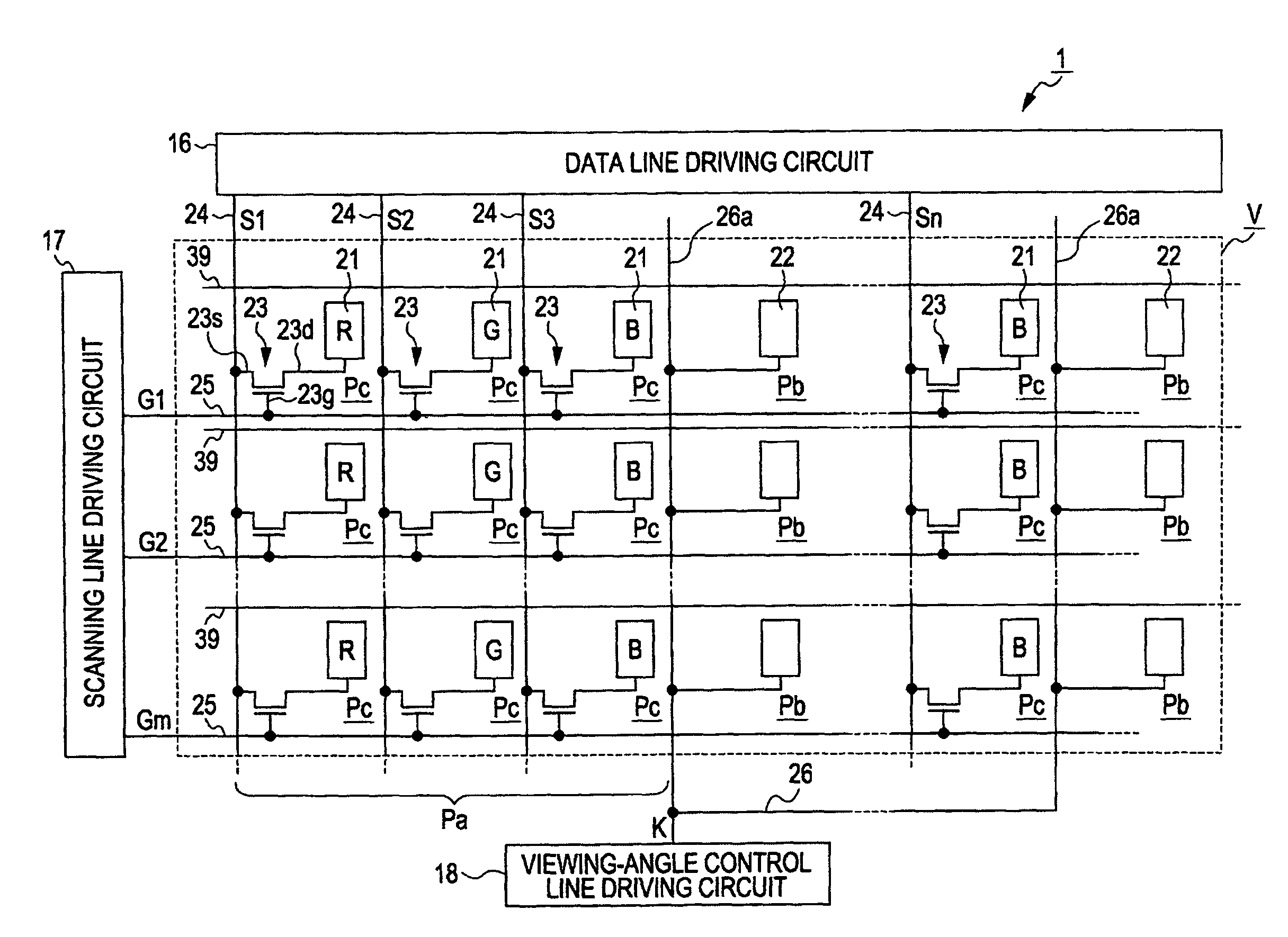
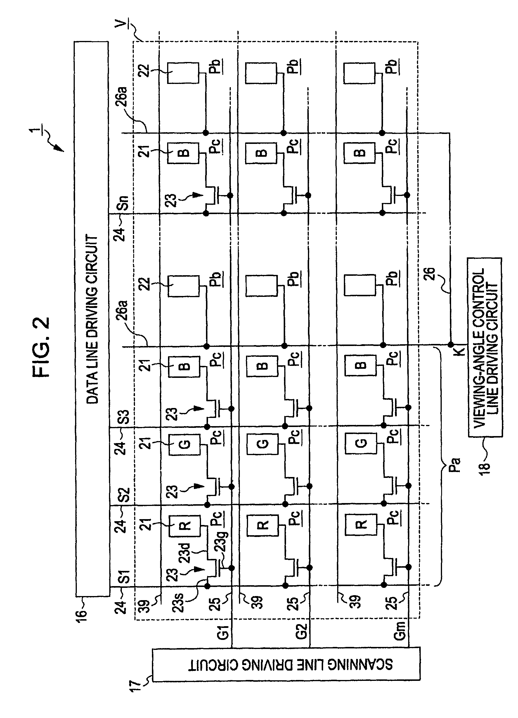
[0083]In the invention, by dividing the image display region V of the liquid crystal device 1 into a plurality of display regions, it is possible to perform different viewing-angle controls (that is, the narrow viewing-angle control and the wide viewing-angle control) on the divided display regions, respectively.

[0084...


PUM

PropertyMeasurementUnit
drive voltageaaaaaaaaaa
azimuthal angleaaaaaaaaaa

Abstract

A liquid crystal device includes a pair of substrates with a liquid crystal layer interposed therebetween. A planar region of the pair of substrates has at least one display pixel region and at least one viewing-angle control pixel region that performs dark display in the front direction of surfaces of the pair of substrates and has brightness variable depending on a viewing angle in an oblique direction to the normal direction of the surfaces of the pair of substrates. A pair of electrodes driving the liquid crystal layer is provided in the display pixel region and the viewing-angle control pixel region. A voltage applied between the pair of electrodes in the viewing-angle control pixel region at the time of driving the liquid crystal layer in the viewing-angle control pixel region is higher than a voltage applied between the pair of electrodes in the display pixel region.

Description

BACKGROUND[0001]1. Technical Field[0002]The present invention relates to a liquid crystal device capable of switching display modes of a wide viewing angle and a narrow viewing angle and an electronic apparatus having the same.[0003]2. Related Art[0004]Recently, a liquid crystal device has come into widespread use in electronic apparatuses such as a mobile phone, a portable information terminal, and a computer display. In such a liquid crystal device, a wide viewing angle characteristic is necessary when many people look at a displayed image in various directions, and a narrow viewing angle characteristic is necessary when it is desired not to show the displayed image to the people around a user.[0005]For this reason, a liquid crystal device capable of switching a display mode between a wide viewing angle and a narrow viewing angle was proposed (for example, refer to JP-A-2007-79525, JP-A-2007-178736, JP-A-2007-178738, JP-A-2007-178739, and JP-A-2003-233074).[0006]In JP-A-2007-79525...

Claims


Application Information

Patent Timeline
Patent Type & Authority Patents(United States)
IPC IPC(8): G02F1/1335G09G3/36G02F1/1343
CPCG09G3/3607G09G3/3648G02F1/134309G02F2001/134372G02F2201/123G02F2201/52G09G2320/068G02F1/134372
Inventor MATSUSHIMA, TOSHIHARU
Owner JAPAN DISPLAY INC
Why Eureka
Try Eureka