Microcatheter

a micro-catheter and catheter technology, applied in the direction of catheters, coatings, etc., can solve the problems of insufficient flow in the lumen, tube bending or twisted at various sites along the entire length of the catheter, and the diameter of the near end side at hand is too small, so as to improve the anti-kinking property, improve the pressure resistance, and improve the effect of approach or access

Inactive Publication Date: 2015-06-30
KAWASUMI LABORITORIES INC
View PDF8 Cites 2 Cited by
  • Summary
  • Abstract
  • Description
  • Claims
  • Application Information

AI Technical Summary

Benefits of technology

[0059]The microcatheter of this invention is improved in pressure resistance and also improved in anti-kinking property, so that when the microcatheter of this invention is used, it is made possible to have a good approach or access to a minute blood vessel superselectively, and it is hence made possible to practice imaging of a blood vessel, administration of dosage, or treatment of embolus, etc., superselectively.EXAMPLES
[0060]Specific embodiments of this invention will be explained with reference to Examples hereinafter. In the following Examples, the hardness of each of inner layers and outer layers are shown as “Shore D hardness” measured with a Shore D hardness tester.Comparative

Problems solved by technology

On the other hand, since a flexible extra fine microcatheter is easily twisted in a passage having a very small radius, which causes a problem wherein a flow in a lumen may be limited or stemmed.
Further, when a microcatheter is moved forward along a passage in a lumen or is made to transmit a torque, the above microcatheter with such an extra fine configuration is not structurally stable, causing a problem that the tube is bent or twisted at various sites along the entire length of the catheter.
When the forward end diameter of the catheter is decreased, therefore, the diameter of that on the near end side at hand is too small, and even if the hardness of the resin is increased, the tube has only insufficient rigidity.
On the other hand, when the diameter on the near end side at hand is increased, the forward end of the catheter is too large, thus involving a problem that the selectivity to a blood vessel is degraded.
Further, since the outer layer tube is not continuously coated with same one material and one layer from the end portion near at hand through the forward end portion, there caused a problem that the adhesion to the braid is poor and that the catheter is inferior in pressure resistance and torque performance.
It is practically difficult to materialize any microcatheter of which the hardness alone is changed without changing outer dimensions of a shaft tube as described in Patent Document 1, and in reality such has not yet been commercialized.
That is, it is constitutionally cut off in the middle of the shaft tube, so that the problem with the catheter is that the adhesion to a braid is poor and that the microcatheter is inferior in pressure resistance and torque performance.
Therefore, these microcatheters have problems similar to those in Patent Document 2.

Method used


Image

  • Microcatheter
  • Microcatheter
  • Microcatheter

Examples


example 1

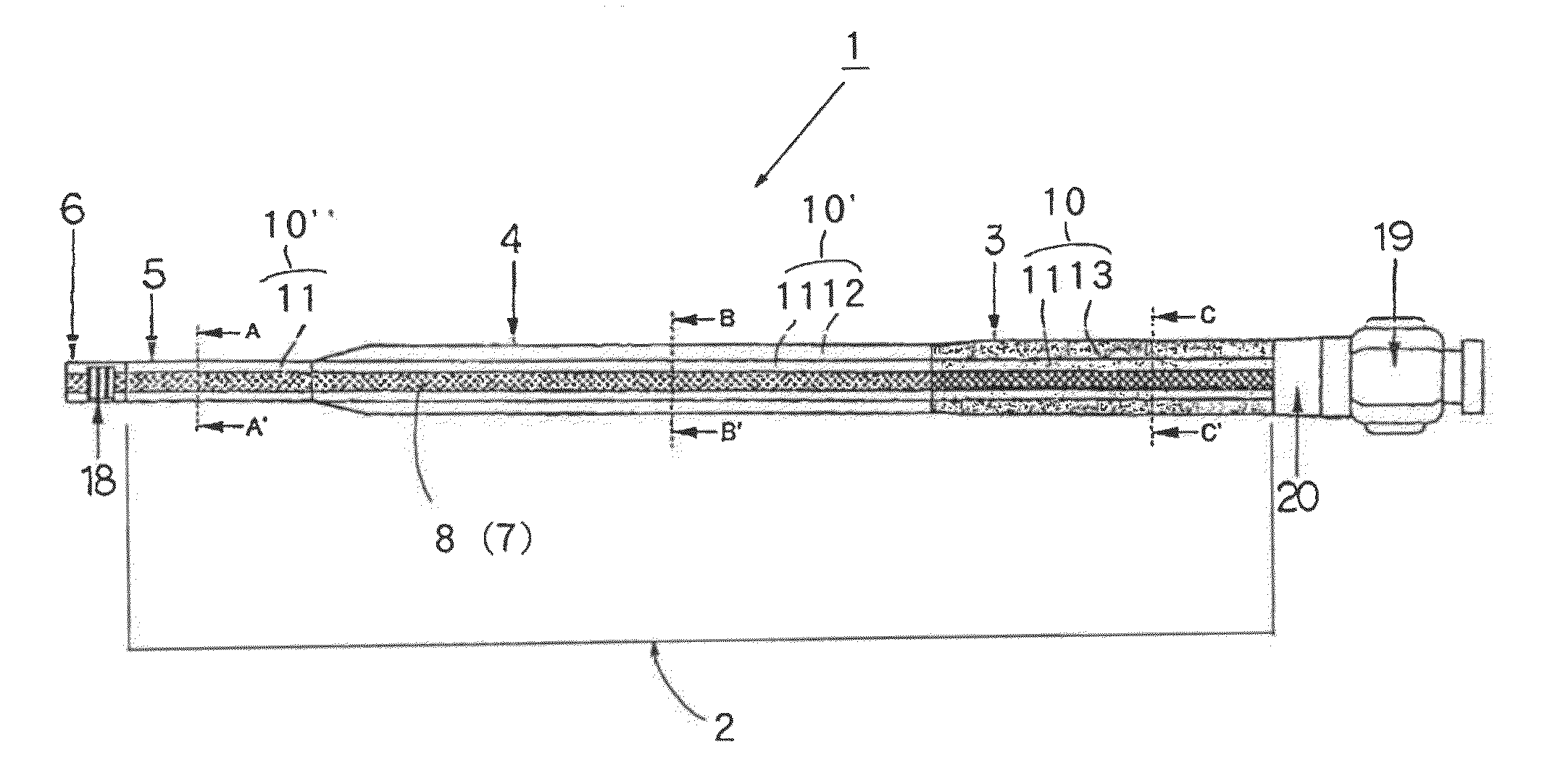
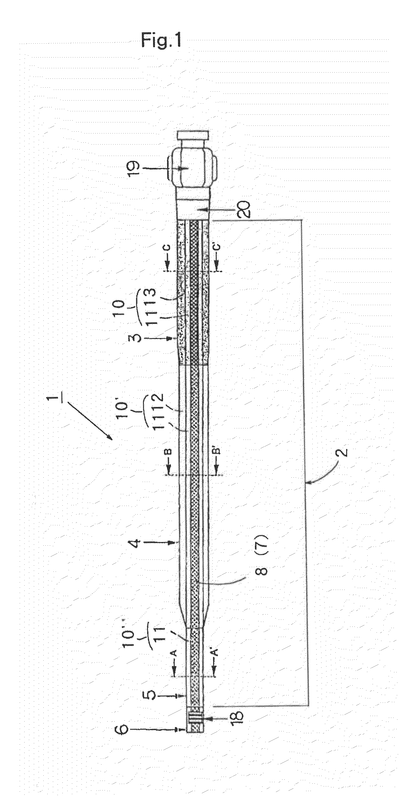
[0066]A shaft tube 2 that was formed of a multilayered tube for a microcatheter and that had a layer structure shown in Table 1 was produced as follows.

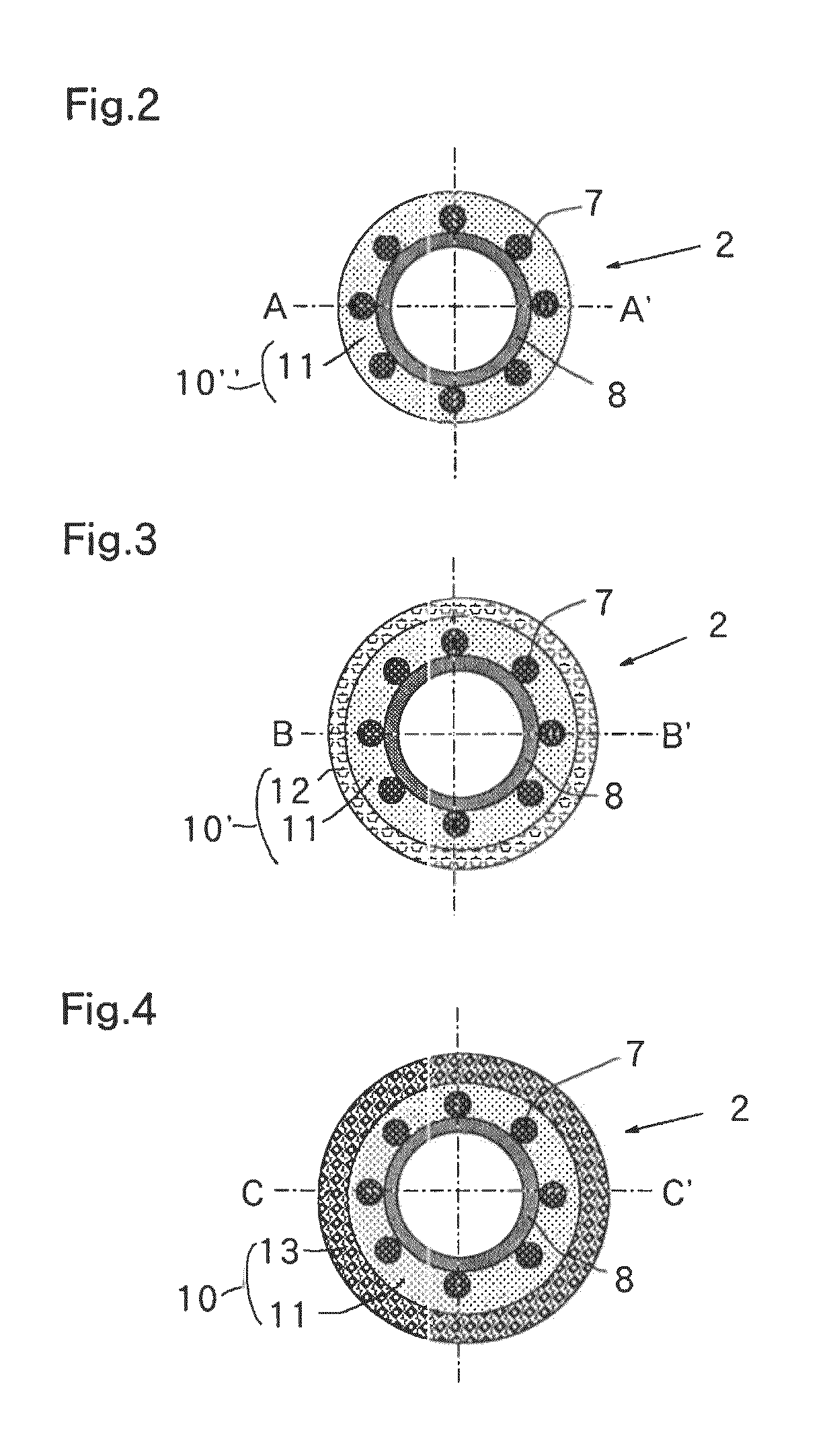
[0067]Sixteen stainless steel wires having a diameter of 0.03 mm each were braided on a PE tube that was employed for an inner layer 8 and that had a resin thickness of 0.015 mm and an internal diameter of 0.56 mm, to coat or cover the outer surface thereof. A first outer layer 11, a second outer layer 12 and a third outer layer 13 were formed thereon by a simultaneous multilayer melt-extrusion with a multilayer extrusion molding machine having a ring die.

[0068]A polyamide elastomer (hardness 55 D) was used as a resin for the first outer layer 11, a polyamide elastomer (hardness 63 D), as a resin for the second outer layer 12, and a polyamide elastomer (hardness 77 D), as a resin for the third outer layer 13. The shaft tube 2 having a distal zone 5 with an outer diameter of 0.73 mm, an intermediate zone 4 with an outer diameter of 0....

example 2

[0076]A shaft tube 2 that was formed of a multilayered tube for a microcatheter and that had a layer structure shown in Table 1 was produced as follows.

[0077]Sixteen stainless steel wires having a diameter of 0.03 mm each were braided on a PTFE tube that was employed for an inner layer 8 and that had a resin thickness of 0.006 mm and an internal diameter of 0.56 mm, to coat or cover the outer surface thereof. A first outer layer 11, a second outer layer 12 and a third outer layer 13 were formed thereon by a simultaneous multilayer melt-extrusion with a multilayer extrusion molding machine having a ring die.

[0078]A polyamide elastomer (hardness 35 D) was used as a resin for the first outer layer 11, a polyamide elastomer (hardness 63 D), as a resin for the second outer layer 12, and nylon 12 (hardness 77 D), as a resin for the third outer layer 13. The shaft tube having a distal zone 5 with an outer diameter of 0.73 mm, an intermediate zone 4 with an outer diameter of 0.85 mm and a p...


PUM

PropertyMeasurementUnit
thicknessaaaaaaaaaa
diameteraaaaaaaaaa
sizeaaaaaaaaaa

Abstract

In a microcatheter, a shaft tube thereof is sectioned into a proximal zone, an intermediate zone, and a distal zone from a connector to the forward end thereof, each being formed of a multilayered tube, including three types of multilayered tubes different in hardness, an inner layer extending along all the zones from the proximal zone to the distal zone of the shaft tube, and a reinforcing material being fitted to the outer circumference of the inner layer, a first outer layer extending along all the zones from the proximal zone to the distal zone of the shaft tube so as to coat, and adhere to, the inner layer and the reinforcing material, to form a base layer structure of the inner layer / reinforcing material / first outer layer, a third outer layer coating the first outer layer of the base layer structure in the proximal zone, a second outer layer coating the first outer layer of the base layer structure in the intermediate zone.

Description

TECHNICAL FIELD[0001]This invention relates to a microcatheter, and more specifically to a flexible microcatheter in which the hardness or flexibility continuously changes along or over nearly the entire length of the microcatheter.[0002]The microcatheter of this invention not only has improved pressure resistance but also an antikinking property by embedding a braid into a plurality of flexible plastic layers different in hardness, and it is accordingly made possible for the microcatheter to approach or has a good access to minute blood vessel superselectively and it is also made possible for it to practice imaging of a blood vessel, administration of dosage, or treatment of embolus, etc., superselectively.BACKGROUND ART[0003]A microcatheter is a catheter that is used for injecting a medicament such as carcinostatic, or the like or a contrast medium (imaging agent) into a peripheral blood vessel of an organ such as a brain, a breast, an abdomen, or the like for practicing procedure...

Claims


Application Information

Patent Timeline
Patent Type & Authority Patents(United States)
IPC IPC(8): A61M25/00
CPCA61M25/0045A61M25/0054A61M25/005A61M25/0012A61M2025/0042A61M25/00
Inventor WATANABE, MASATOSHIHORIKAWA, KOJI
Owner KAWASUMI LABORITORIES INC
Why Eureka
Try Eureka