
Jig for firearm lower receiver manufacture

a lower receiver and chuck technology, applied in the field of chuck for firearm lower receiver manufacture, can solve the problems of difficult for many customers to manufacture, machining must be done, and many customers do not have the equipment to properly manufacture the last twenty percent of the lower receiver

Active Publication Date: 2015-04-21
BLACKHAWK MFG GRP INC
View PDF20 Cites 34 Cited by
  • Summary
  • Abstract
  • Description
  • Claims
  • Application Information

AI Technical Summary

Benefits of technology

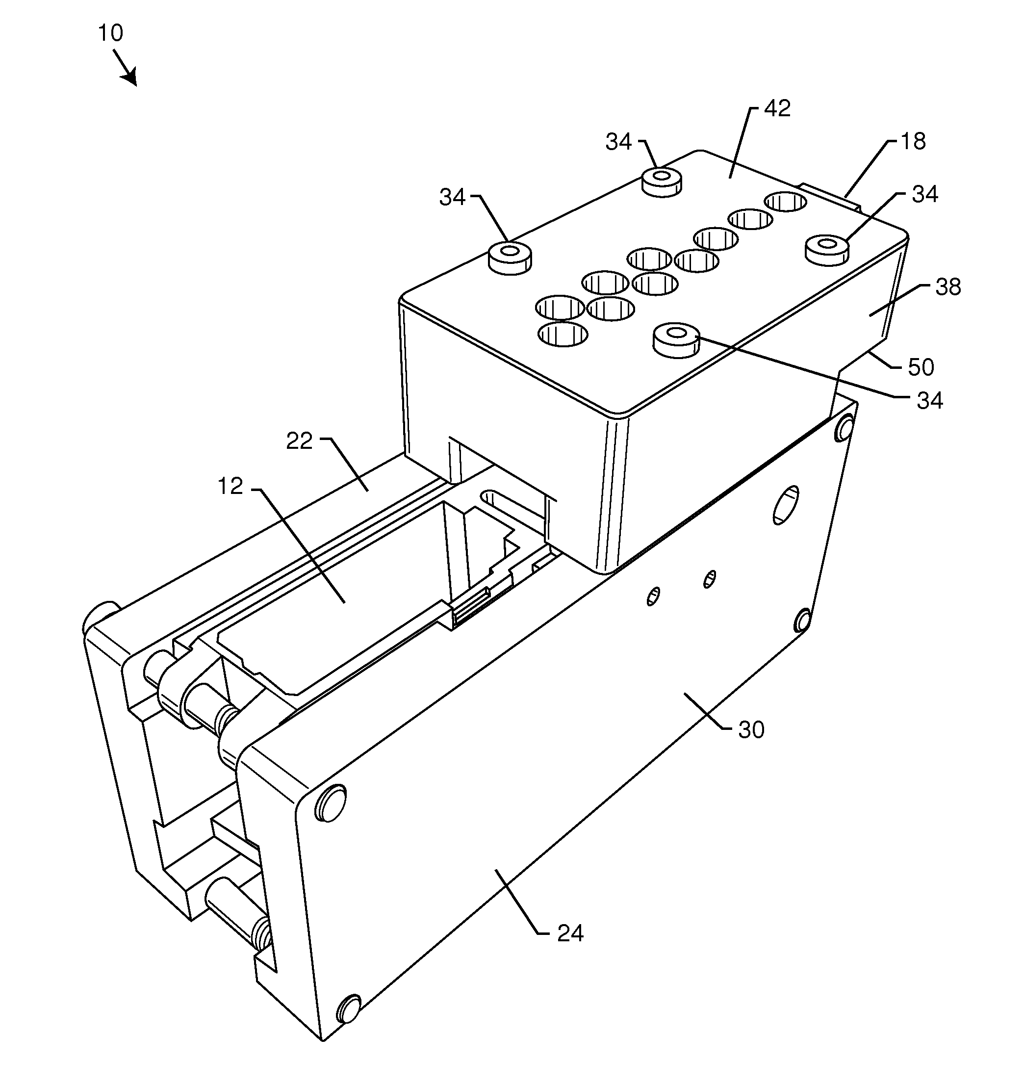
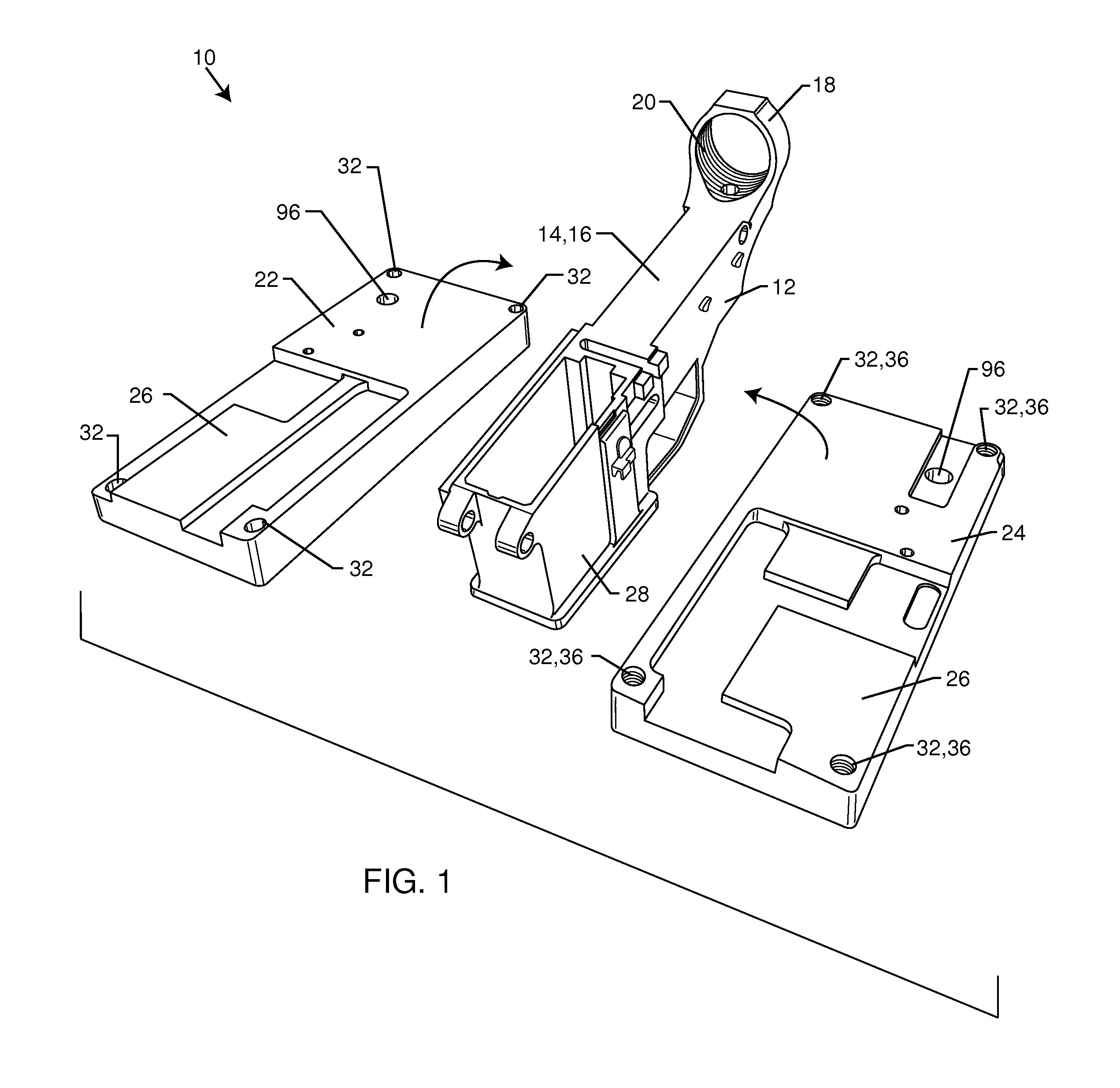
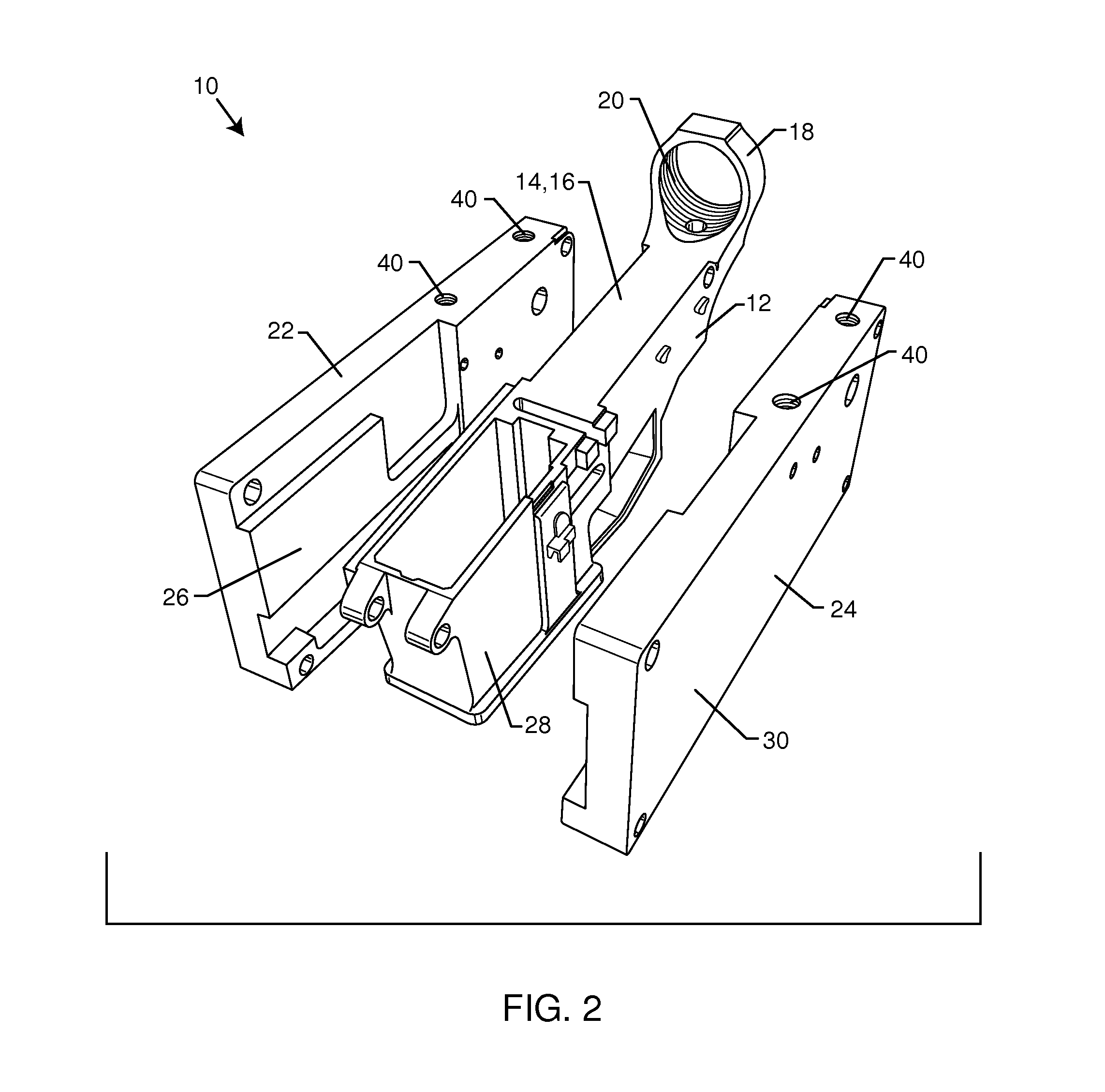
The patent describes a tool assembly for manufacturing a firearm lower receiver. The assembly includes a plurality of separate components that are used to attach a firearm lower receiver in place. These components include a drill block jig, a template spacer jig, a first pocket template, a second pocket template, a router support plate, and a depth gauge feature. The drill block jig has through holes that align with the top surface of the firearm lower receiver and is used to secure the lower receiver in place. The template spacer jig and the first and second pocket templates have through holes that align with the top surface of the firearm lower receiver. The router support plate has a router aperture that aligns with the top surface of the firearm lower receiver. The depth gauge feature includes a slot formed in the first surface of the firearm lower receiver. The assembly tooling helps to accurately manufacture firearm lower receivers.

Problems solved by technology

However, many customers do not have the equipment to properly manufacture the last twenty percent of the lower receiver.
Also, the machining must be done precisely, which is hard for many customers to do.

Method used


Image

  • Jig for firearm lower receiver manufacture
  • Jig for firearm lower receiver manufacture
  • Jig for firearm lower receiver manufacture

Examples


Embodiment Construction

[0054]Part of the last twenty percent of manufacture of a lower receiver requires the use of a mill or a drill press that is acting like a mill. However, many customers do not have access to a mill as mills are extremely large and expensive machines. The customer then attempts to use a drill press as a mill. This is extremely difficult to do as a drill press is not designed to properly mill in a direction perpendicular to the drilling axis. This is also complicated because the customer must manually move the part relative to the drill press. Manually moving the part is difficult to do accurately as compared to a proper milling machine. This complication frequently leads to a frustrated customer and a destroyed / ruined lower receiver.

[0055]The embodiments taught herein solves this problem and eliminates the need for a mill or a drill press as a mill. The embodiments herein are a novel jig assembly that is designed to accept the use of a router. A router is similar to a mill in that it...


PUM

PropertyMeasurementUnit
thicknessaaaaaaaaaa
depthaaaaaaaaaa
shapeaaaaaaaaaa

Abstract

A machining tool assembly for manufacturing a firearm lower receiver includes a first and second side jig which are configured to be disposed on opposite sides of the firearm lower receiver and configured to removably attach to one another securing the firearm lower receiver therebetween. A drill block jig is removably attachable to the first and second side jigs disposed above the top surface of the firearm lower receiver, wherein the drill block jig comprises a plurality of through holes. A template spacer jig is removably attachable to the first and second side jigs disposed above the top surface of the firearm lower receiver, wherein the template spacer jig comprises a spacer aperture disposed through a template spacer thickness. A first and second pocket templates are removably attachable and disposed onto the template spacer jig. A router support plate is disposed onto either the first or second pocket templates.

Description

CROSS-REFERENCE TO RELATED APPLICATIONS[0001]This application claims priority to provisional application 61 / 902,357 filed on Nov. 11, 2013, the entire contents of which are hereby incorporated by reference.FIELD OF THE INVENTION[0002]The present invention generally relates to firearm manufacture. More particularly, the present invention relates to a jig that is sent to a customer along with an 80% completed lower receiver of an AR15 for the customer to finish manufacturing the firearm themselves.BACKGROUND OF THE INVENTION[0003]There exists a market for partially manufactured lower receivers for AR-15 firearms. An AR-15 is a semi-automatic rifle that has been in commerce and use for decades. The AR-15 is comprised of many individual parts. It is the lower receiver that is technically classified as a firearm and regulated as such. Partially manufactured lower receivers are referred to as 80% lower receivers, meaning that about eighty percent of the manufacturing has been completed. I...

Claims


Application Information

Patent Timeline
Patent Type & Authority Patents(United States)
IPC IPC(8): B23Q17/22G01B5/14G01B5/18
CPCG01B5/14G01B5/18F41A3/66Y10T29/49771Y10T29/49778B23Q3/00B23P13/00
Inventor CHANG, CHARLES E.PARTINGTON, WAYNE R.SMITH, II, TILDEN A.DE NEVE, JULES JOHANNES
Owner BLACKHAWK MFG GRP INC
Learn More