
Passive underground flood protection

a flood protection and underground technology, applied in the direction of lighting and heating equipment, heating types, vertical ship lifting, etc., can solve the problems of subsystems that fail or at least operate poorly or inefficiently, passengers and operators of underground transportation systems may be negatively affected, subsystems may fail, malfunction, etc., to achieve the effect of preventing flood damage, preventing flood damage, and preventing flood damag

Inactive Publication Date: 2015-04-14
NEW YORK CITY TRANSIT AUTHORITY A NY
View PDF9 Cites 14 Cited by
  • Summary
  • Abstract
  • Description
  • Claims
  • Application Information

AI Technical Summary

Benefits of technology

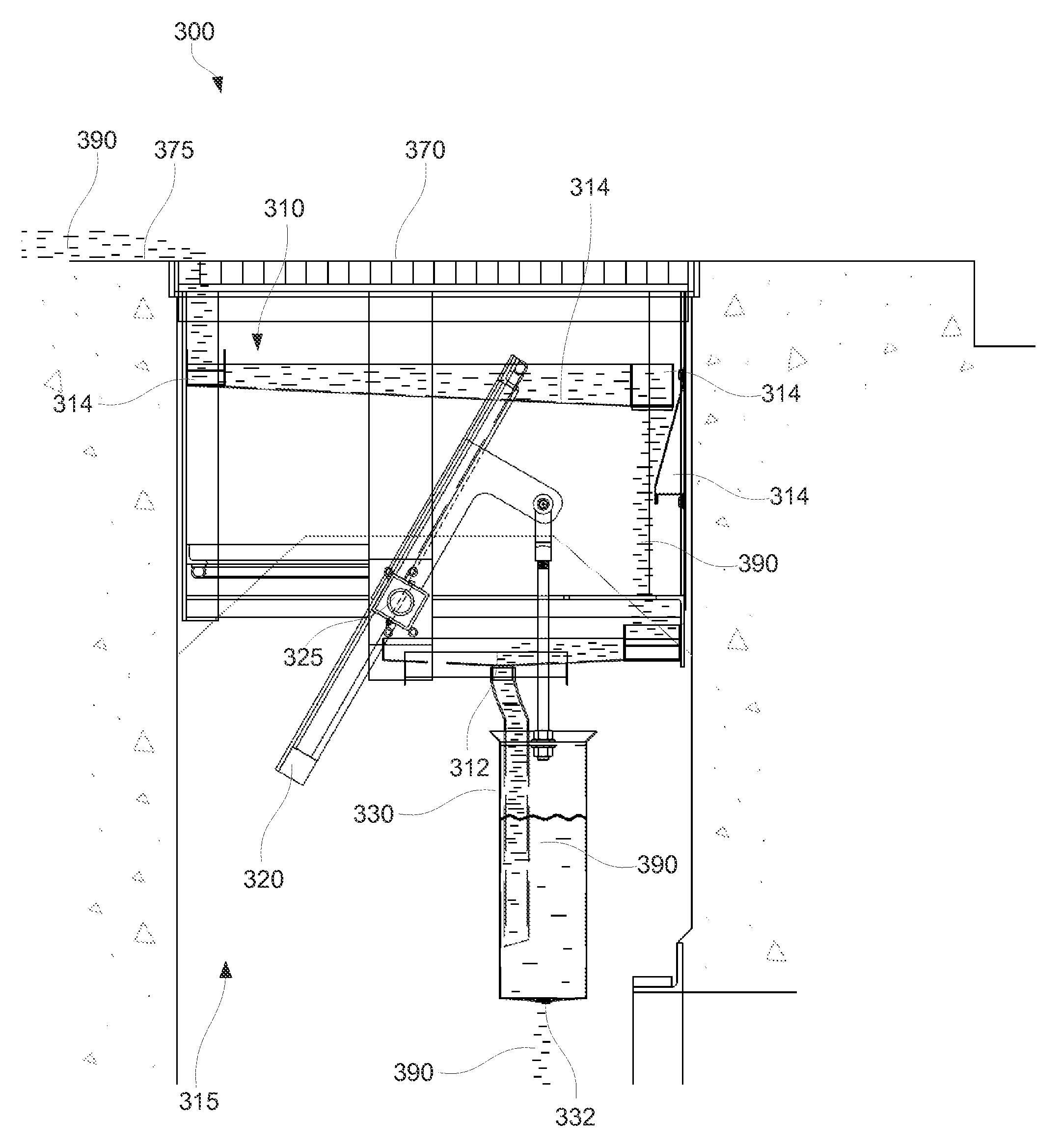
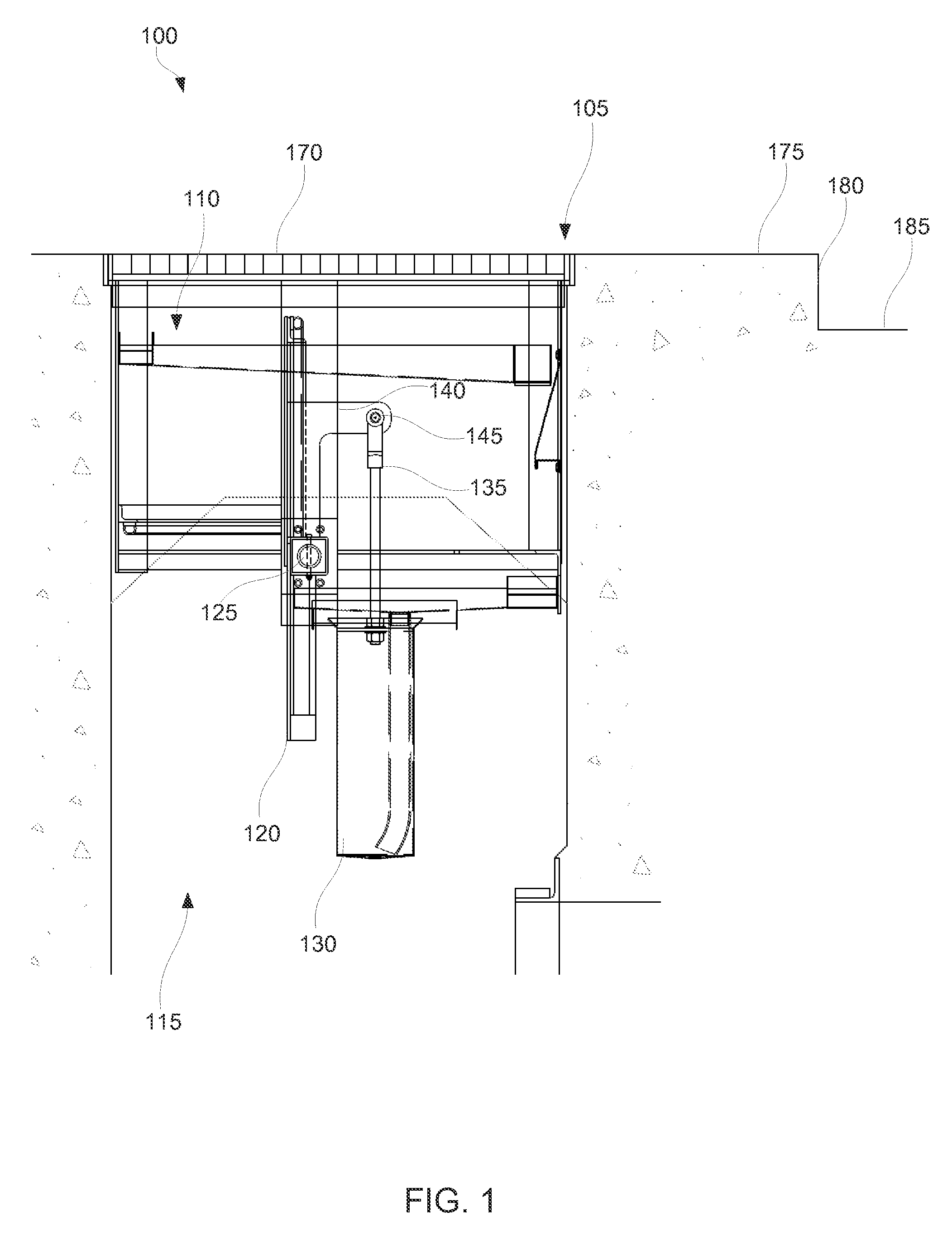
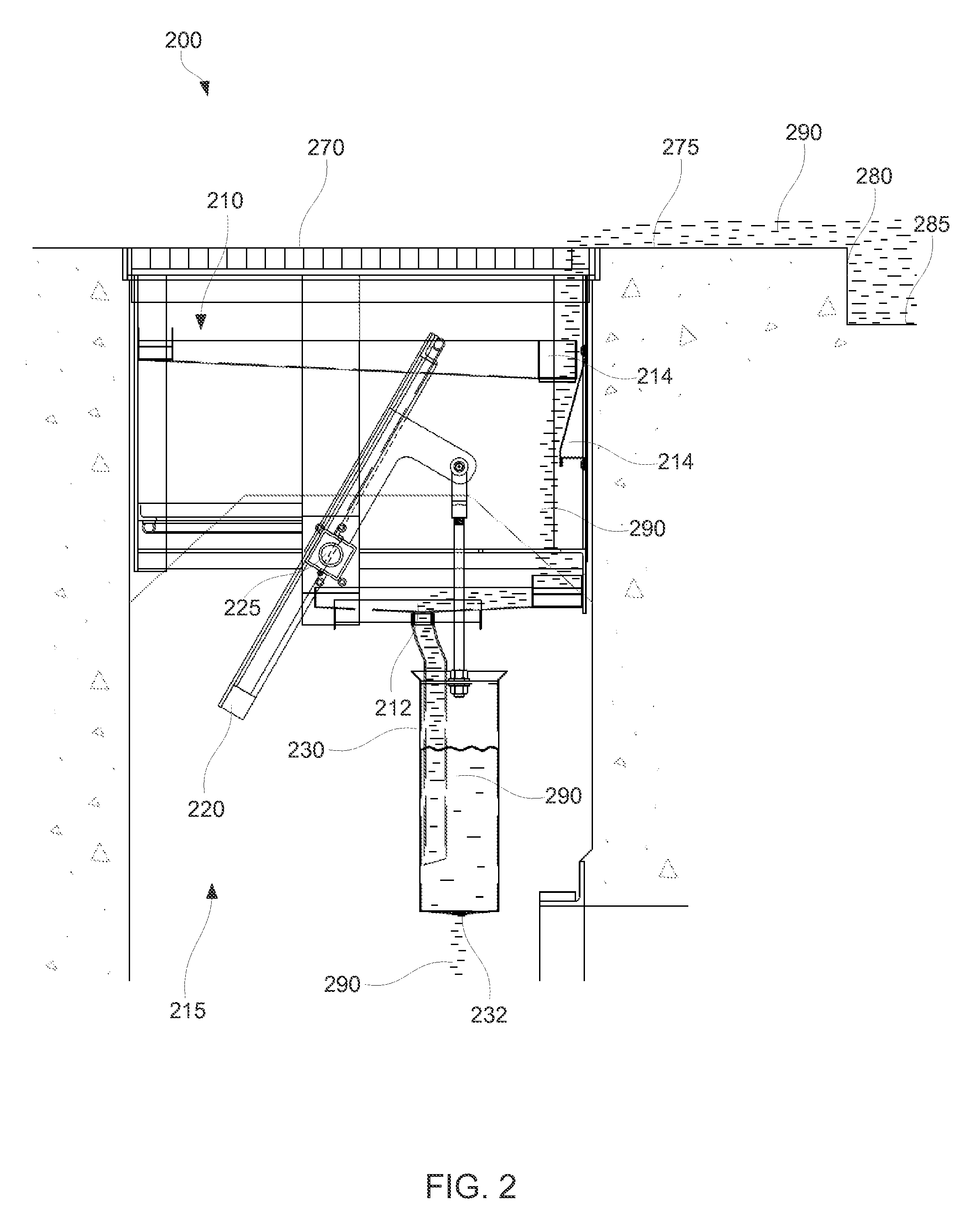
The patent text discusses methods, systems, devices, and / or apparatus related to reducing and restricting water from entering underground transportation systems. The technical effect of the patent text is to provide a way to prevent water from entering underground systems via vents, which can cause damage and malfunctions to the subsystems. The methods, systems, devices, and / or apparatus described in the patent text may use mechanical closure devices or other means to control the flow of water and maintain optimal conditions for underground transportation systems.

Problems solved by technology

Many of these subsystems typically fail or at least operate poorly or inefficiently when in contact with water, whether from environmental or man-made causes.
If air quality is not maintained at an acceptable level, then passengers and operators of the underground transportation system may be negatively affected.
Similarly, if the operating temperatures are not maintained at an acceptable level, then subsystems may fail, malfunction, and / or operate inefficiently.
Rain, for example, may temporarily cause flooding in underground transportation systems.
Similarly, water from fire hydrants on the surface may also flood underground transportation systems.
Such water may cause pooling of water on, near, or over certain components of subsystems, causing failures, malfunctions, and / or inefficiencies of such subsystems.
Such pumping can be inadequate in times of surface flooding due to heavy rain.

Method used


Image

  • Passive underground flood protection
  • Passive underground flood protection
  • Passive underground flood protection

Examples


Embodiment Construction

[0012]In the following detailed description, reference is made to the accompanying drawings, which form a part hereof. In the drawings, similar symbols identify similar components, unless context dictates otherwise. The illustrative embodiments described in the detailed description, drawings, and claims are not meant to be limiting. Other embodiments may be utilized, and other changes may be made, without departing from the spirit or scope of the subject matter presented here. It will be readily understood that the aspects of the present disclosure, as generally described herein, and illustrated in the Figures, may be arranged, substituted, combined, and designed in a wide variety of different configurations, each of which are explicitly contemplated and made part of this disclosure.

[0013]This disclosure is generally drawn to methods, systems, devices and / or apparatus related to reducing and / or restricting water from entering underground systems. Specifically, the disclosed methods,...


PUM


Abstract

Some examples provide methods, systems, devices and / or apparatus related to reducing and / or restricting water from entering underground transportation system, and more Specifically, to reducing and / or restricting water from entering underground transportation systems via vents based on the weight of the water, while not restricting ventilation airflow when water is not present. Some example systems for restricting water flow in a surface vent may include a frame that receives water, a door pivotally coupled to the frame(where the door may pivot between a first position and a second position), and a reservoir pivotally coupled to the door. The reservoir may collect the received water and may cause the door to pivot between the first position and the second position based on weight of the collected water.

Description

BACKGROUND[0001]Underground systems such as underground transportation systems conventionally employ many electrical and mechanical subsystems to maintain operation. For example, underground transportation systems (e.g., subways, trains) typically incorporate ventilation subsystems, power subsystems, control subsystems, and the like. Many of these subsystems typically fail or at least operate poorly or inefficiently when in contact with water, whether from environmental or man-made causes.[0002]Ventilation subsystems, for example, typically operate to remove gases and particles from the air and to maintain operating temperatures of the underground transportation system. In this manner, the quality of breathable air underground and the operating temperatures are maintained at acceptable levels for the passengers and the technical requirements of the subsystems, respectively. If air quality is not maintained at an acceptable level, then passengers and operators of the underground tran...

Claims


Application Information

Patent Timeline
Patent Type & Authority Patents(United States)
IPC IPC(8): E02B5/08
CPCE02B5/082E03F5/0411F24F13/14F24F13/1406F24F13/1426Y10T137/7339Y10T137/7355
Inventor PETRILLO, STEPHEN
Owner NEW YORK CITY TRANSIT AUTHORITY A NY
Learn More