Computer system and management server

a computer system and management server technology, applied in computing, instruments, electric digital data processing, etc., can solve the problems of logical device names not being matched with device names, different device configurations at startup of os, and inability to automatically and uniquely identify the type of added or replaced pci devices. to achieve the effect of ensuring the consistency of device nam

Inactive Publication Date: 2015-03-24
HITACHI LTD
View PDF11 Cites 0 Cited by
  • Summary
  • Abstract
  • Description
  • Claims
  • Application Information

AI Technical Summary

Benefits of technology

[0012]This invention has been accomplished in view of the aforementioned problems and aims to provide a computer system and a management server that assure the consistency in device names of the devices, even if the device configuration at a startup of the OS is different from the previous one.
[0015]This invention assures the consistency in device names of the devices, even if the device configuration at an OS startup is different from the previous one.

Problems solved by technology

The above-listed techniques, however, have a problem that, when a PCI device for a computer is added or replaced, the operating system (OS) installed in the computer cannot automatically and uniquely identify the type of the added or replaced PCI device.
However, the device configuration at the startup of the OS may be different from the device configuration at the previous startup because of addition or replacement of a PCI device.
This method, however, has a problem that, if hardware identification information or software identification information used in assigning the logical device names is cleared by initialization or duplicated by backup, the logical device names cannot be matched with the device names so that a device to be accessed might not be located.

Method used


Image

  • Computer system and management server
  • Computer system and management server
  • Computer system and management server

Examples


first embodiment

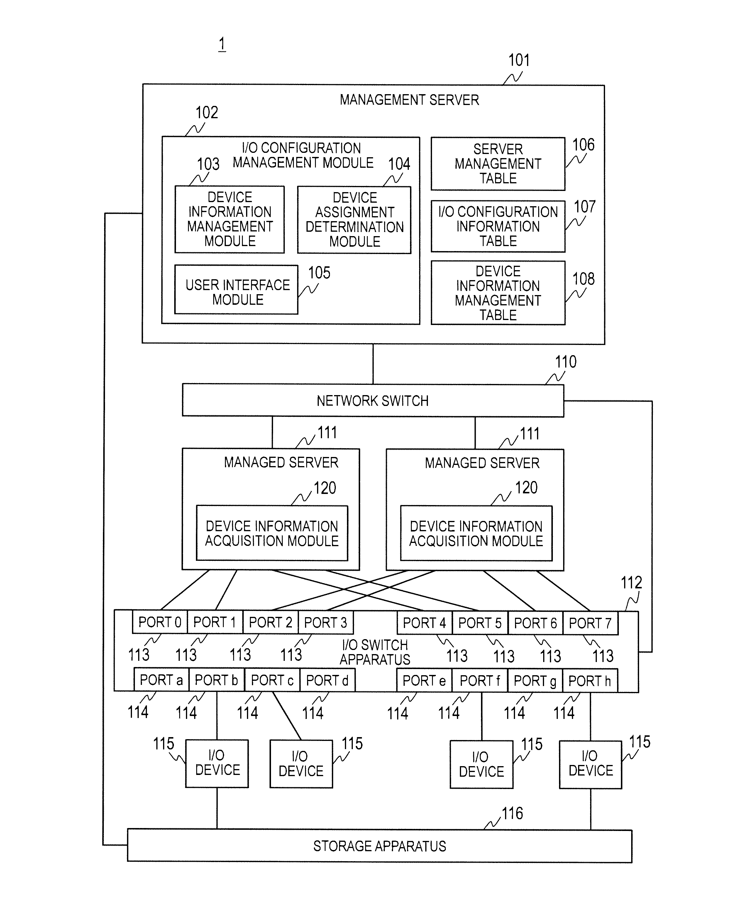
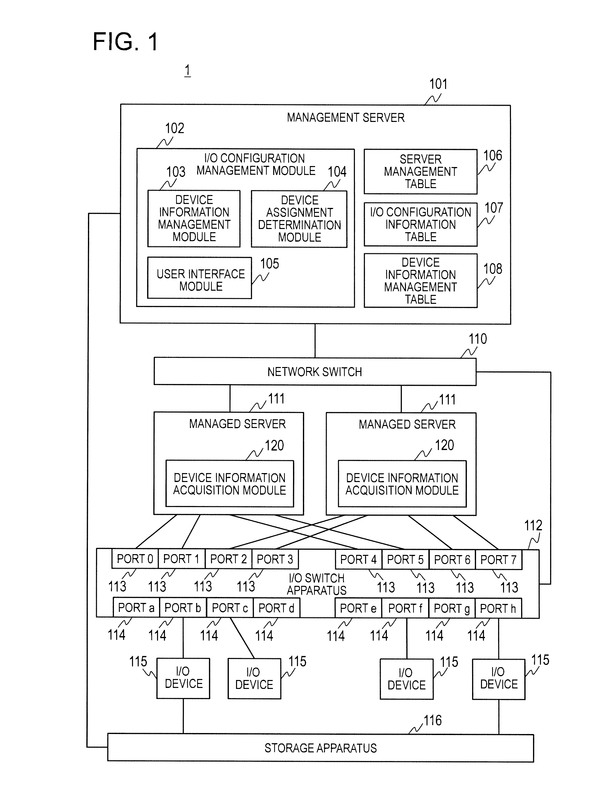
[0043]FIG. 1 is a diagram illustrating an overall configuration example of the computer system 1 in the first embodiment of this invention. The computer system 1 shown in FIG. 1 includes a management server 101, a network switch 110, a plurality of managed servers 111, an I / O switch apparatus 112, a plurality of I / O devices 115, and a storage apparatus 116.

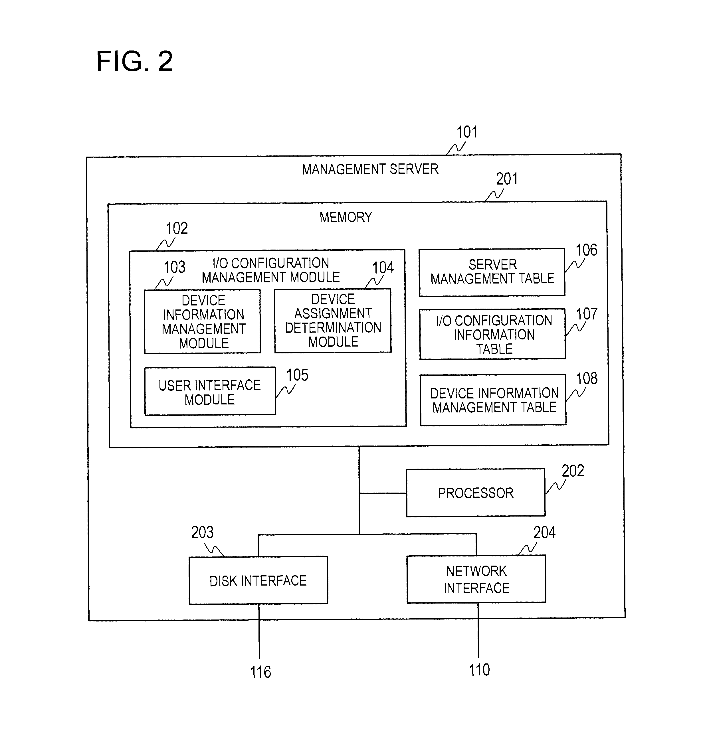
[0044]The management server 101 is a computer apparatus for managing the logical configuration of the I / O devices 115 recognized by the OS of the managed servers 111 and the physical configuration of the I / O devices 115 managed by the I / O switch apparatus 112 together. The management server 101 includes an I / O configuration management module 102, a server management table 106, an I / O configuration information table 107, and a device information management table 108. Each element is described later.

[0045]The management server 101 receives a notice of change in the logical configuration or the physical configuration of I / O devices 1...

second embodiment

[0115]The foregoing first embodiment described an example where the device configuration is changed because of addition of a new I / O device 115. The second embodiment describes a case where the device configuration is changed because of installment (addition), removal, or replacement of an I / O device 115. Hereinafter, differences from the foregoing first embodiment are mainly described and repetitive explanation is omitted as appropriate.

[0116]FIG. 11 is a diagram illustrating an overall configuration example of the computer system 1 in the second embodiment of this invention.

[0117]In the management server 101 shown in FIG. 11, the I / O configuration management module 102 further includes a user policy processing module 118. The management server 101 also includes an I / O switch physical configuration table 107a, an I / O switch server connection information table 107b, and a user policy management table 119. The I / O switch physical configuration table 107a and the I / O switch server con...


PUM


Abstract

A computer system includes an I / O switch connected to a computer and changing connections between the computer and I / O devices, and a management server for managing configuration of the I / O devices. The management server, with respect to existing I / O devices connected to the I / O switch, stores information representing logical configuration of the existing I / O devices recognized by an OS of the computer and information representing physical configuration of the existing I / O devices managed by the I / O switch in the memory, The management server, upon receipt of a notice indicating a change in the configuration of the existing I / O devices from the I / O switch, changes the physical configuration of the existing I / O devices after the change in the configuration to be matched with the logical configuration of the existing I / O devices and instructs the I / O switch to change the connections in accordance with the changed physical configuration.

Description

CROSS-REFERENCE TO RELATED PATENT APPLICATIONS[0001]The present application claims priority from Japanese patent application No. 2010-278580 filed on Dec. 14, 2010, the content of which is hereby incorporated by reference into this application.BACKGROUND OF THE INVENTION[0002]This invention relates to a computer system and a management server.[0003]In recent years, PCI Express Switches (hereinafter, referred to as PCIeSW) are becoming more common in practical use; the number of PCI devices that can be mounted on a single computer has increased ten times as many as before. Such PCI devices support various functions including hot plug; accordingly, it is easy to add or replace a PCI device for a computer.[0004]Various techniques related to the PCI device are disclosed (for example, refer to Patent Literature 1, Patent Literature 2, and Patent Literature 3).[0005]Patent Literature 1: JP 2006-195870 A[0006]Patent Literature 2: JP 2009-294828 A[0007]Patent Literature 3: JP 2008-152787ASU...

Claims


Application Information

Patent Timeline
Patent Type & Authority Patents(United States)
IPC IPC(8): G06F3/00G06F9/44G06F13/10G06F13/14
CPCG06F9/4411G06F13/10G06F13/14G06F13/4022G06F2213/3802G06F2213/3808
Inventor TODA, MASARUHOSONO, ISAMUUCHIDA, TOMOHITO
Owner HITACHI LTD
Why Eureka
Try Eureka