Oil separator

a technology of oil separator and separator plate, which is applied in the direction of separation process, filtration separation, machine/engine, etc., can solve the problems of high production cost and increase in the number of types, and achieve the effect of simple low-cost structur

Inactive Publication Date: 2015-02-24
TOYOTA BOSHOKU KK
View PDF14 Cites 2 Cited by
  • Summary
  • Abstract
  • Description
  • Claims
  • Application Information

AI Technical Summary

Benefits of technology

[0007]In view of the above, the invention has been made, and it is an object of the invention to provide an oil separator that has a simple low-cost structure and can be applied to various types of engines.
[0013]According to the oil separator of the present embodiments, includes: a housing provided independently of a body of an engine; and a gas-liquid separation unit which is provided in the housing and separates blow-by gas into a gas component and an oil component. The housing includes: a lead-in port which is provided on the upstream side of the gas-liquid separation unit and through which the blow-by gas is led in; a lead-out port which is provided on the downstream side of the gas-liquid separation unit and through which the gas component is led out; and a drain port which is provided on the downstream side of the gas-liquid separation unit and through which the oil component is discharged. Thus, the blow-by gas led into the housing from the lead-in port is separated by the gas-liquid separation unit into the gas component and the oil component, which gas component is led out of the housing through the lead-out port and which oil component is discharged out of the housing through the drain port. Further, the housing has an attachment portion inside to which a plurality of types of gas-liquid separation units can be attached, to which a selected one of a plurality of types of gas-liquid separation units is attached. Thus, an appropriate gas-liquid separation unit can be selected in accordance with an engine type and performance requirements and attached to the attachment portion. Consequently, the invention can be applied to various types of engines. Further, by using a common housing and a common forming die for a plurality of types of gas-liquid separation units, it is possible to reduce cost and simplify processes, thereby providing a simple low-cost structure.
[0014]Further, when the housing includes a first case and a second case whose connecting circumferential surfaces are connected, the attachment portion includes a first attachment portion provided along and in the vicinity of the connecting circumferential surface of the first case and a second attachment portion provided along and in the vicinity of the connecting circumferential surface of the second case, and the gas-liquid separation unit is sandwiched by the first attachment portion and the second attachment portion, connecting position of the first and second cases and an attaching position of the gas-liquid separation unit are adjacent to each other, so that the first and second cases and the gas-liquid separation unit can be connected using a common connecting portion. Consequently, ease of assembly for the oil separator further is improved.
[0015]Further, when the housing includes a first case and a second case whose connecting circumferential surfaces are connected with each other and the attachment portion is provided on one of the first and second cases, it is possible to attach the gas-liquid separation unit to the attachment portion on one of the first and second cases and then connect the first and second case to face each other. Consequently, ease of assembly for the oil separator is improved.
[0016]Further, when the housing includes a first case and a second case whose connecting circumferential surfaces are connected with each other, the attachment portion includes a first attachment portion which has a concave-shaped vertical section and is provided on the first case and a second attachment portion which has a concave-shaped vertical section and is provided on the second case, and the gas-liquid separation unit is sandwiched by the first attachment portion and the second attachment portion, it is possible to attach the gas-liquid separation unit to one of the attachment portions and then connect the first and second cases to face each other. Consequently, ease of assembly for the oil separator is improved.

Problems solved by technology

Consequently, even if the oil separator is provided independently of a body of an engine, it is used only as an exclusive component of the engine of respective types and may contribute to an increase in number of types of the components, giving rise to a problem in high production cost.

Method used


Image

  • Oil separator
  • Oil separator
  • Oil separator

Examples


example

[0045]The following will specifically describe the invention for the first through third embodiments with reference to the drawings.

first embodiment

(1) Configuration of Oil Separator

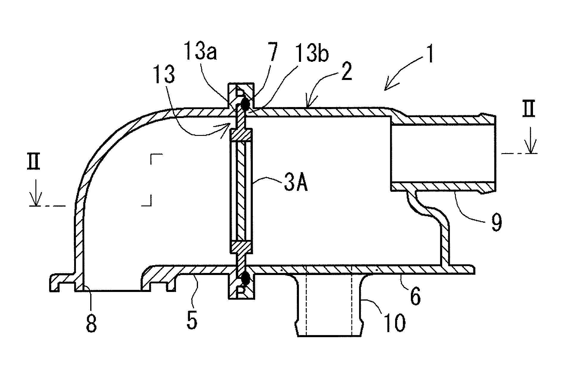
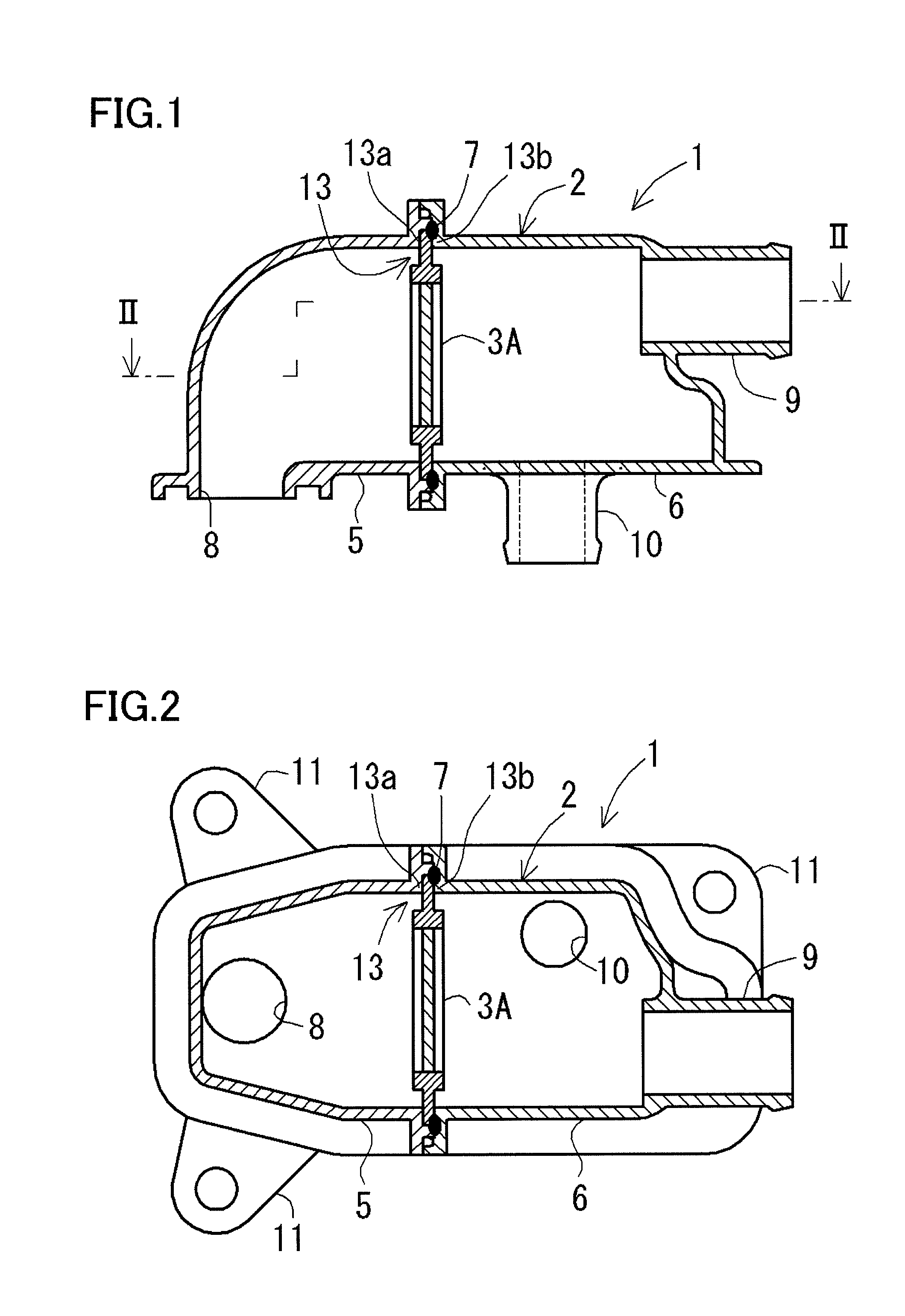
[0046]An oil separator 1 according to the present embodiment is an oil mist separator for capturing oil mist contained in blow-by gas generated in an engine (not shown), as shown in FIGS. 1 and 2. The oil separator 1 includes a housing 2 provided independently of a body of the engine and a gas-liquid separation unit 3A (3B, 3C) which is provided in the housing 2 and separates the blow-by gas into a gas component and an oil component.

[0047]The housing 2 includes first and second cases 5 and 6 made of resin, whose connecting circumferential surfaces 5a and 6a (see FIG. 6) are connected with each other at a welded portion 7 using vibration welding. The first case 5 has a hole-shaped lead-in port 8 which is provided on the upstream side of the gas-liquid separation unit 3A (3B, 3C) and through which blow-by gas is led in. Further, the second case 6 has a tube-shaped lead-out port 9 which is provided on the downstream side of the gas-liquid separation un...

second embodiment

(1) Configuration of Oil Separator

[0059]An oil separator 21 according to the present embodiment is an oil mist separator for capturing oil mist contained in blow-by gas generated in an engine (not shown), as shown in FIGS. 8 and 9. The oil separator 21 includes a housing 22 provided independently of a body of the engine and a gas-liquid separation unit 23A (23B, 23C) which is provided in the housing 22 and separates the blow-by gas into a gas component and an oil component.

[0060]The housing 22 includes first and second cases 25 and case 26 made of resin, whose connecting circumferential surfaces 25a and 26a (see FIG. 13) are connected with each other at a welded portion 27a using vibration welding. The first case 25 has a hole-shaped lead-in port 28 which is provided on the upstream side of the gas-liquid separation unit 23A (23B, 23C) and through which blow-by gas is led in and a tube-shaped drain port 30 which is provided on the downstream side of the gas-liquid separation unit 23...


PUM

PropertyMeasurementUnit
pressure lossaaaaaaaaaa
volumeaaaaaaaaaa
circumferenceaaaaaaaaaa

Abstract

The present oil separator is an oil separator for capturing oil contained in blow-by gas generated in an engine, and includes a housing provided independently of a body of the engine and a gas-liquid separation unit which is provided in the housing and separates blow-by gas into a gas component and an oil component. The housing includes a lead-in port through which the blow-by gas is led in, a lead-out port through which the gas component is led out, and a drain port through which the oil component is discharged. And the housing has an attachment portion inside to which a plurality of types of the gas-liquid separation units respectively are attachable, to which attachment portion, selected one of the plurality of types of gas-liquid separation units is attached.

Description

CROSS-REFERENCE TO RELATED APPLICATIONS[0001]The present application claims priority under 35 U.S.C. §119 of Japanese Application No. 2012-118992 filed on May 24, 2012, the disclosure of which is expressly incorporated by reference herein in its entirety.BACKGROUND OF THE INVENTION[0002]1. Field of the Invention[0003]The invention relates to an oil separator and, more specifically, to an oil separator that has a simple low-cost structure and can be applied to various types of engines.[0004]2. Description of Related Art[0005]Conventionally, a so-called positive crankcase ventilation (PCV) system has been known, which separates oil mist from blow-by gas generated in an engine and returns an oil component to an oil pan and a gas component to an induction system for re-combustion. As an oil separator used in the PCV system, those that utilize inertial collision or filtration by use of a filter have been known (see, for example, JP 2009-68471A and JP 2004-211670A).[0006]The oil separator...

Claims


Application Information

Patent Timeline
Patent Type & Authority Patents(United States)
IPC IPC(8): B01D46/00B01D45/08F01M13/04
CPCB01D45/08F01M13/04Y10S55/19F01M2013/0433F01M2013/0438
Inventor HORIUCHI, YOJI
Owner TOYOTA BOSHOKU KK
Why Eureka
Try Eureka