Sliding bearing and method to perform service at a sliding bearing

a sliding bearing and sliding technology, applied in the direction of sliding contact bearings, bearing repair/replacement, machines/engines, etc., can solve the problems of higher friction, defects or damages, and higher wear of bearings

Active Publication Date: 2015-01-20
SIEMENS GAMESA RENEWABLE ENERGY AS
View PDF5 Cites 9 Cited by
  • Summary
  • Abstract
  • Description
  • Claims
  • Application Information

AI Technical Summary

Benefits of technology

[0024]The grooves and scratches lead to a weaker lubrication, especially a thinner layer of lubricant in the bearing, and therefore to a higher wear.
[0056]After the machining operation loose particles from the surface of the bearing shell or the machining element might be in the bearing. Thus the bearing is cleaned after the machining. The bearing is flushed with a liquid to remove the loose particles and the dust from the bearing. Loose particles and dust can cause damage in the sliding bearing. Oil can be used as a liquid for flushing the bearing. Thus the loose particles and the dust are removed from the bearing. Thus no damage can be done to the sliding surface due to loose particles. Thus the lifetime of the bearing is increased.

Problems solved by technology

These particles can cause defects or damages like scratches in the sliding surface of the bearing.
Defects in the sliding surface again lead to a higher friction that leads to a higher wear in the bearing.
After some time of operation the bearing or parts of the bearing need to be exchanged during service because of damages in the sliding surface.
This makes it very difficult to exchange it.
The exchange of a bearing in a wind turbine, especially a bearing in the drive train, is very complicated and costly.
Especially in the case of an off-shore installation this exchange is very expensive, as a specialized vessel is needed to perform the crane lift.
Little defects like scratches have a negative effect on the lubrication and on the condition of the bearing pads.
The exchange of the bearing is very time consuming and expensive and needs to be avoided as long as possible.

Method used


Image

  • Sliding bearing and method to perform service at a sliding bearing
  • Sliding bearing and method to perform service at a sliding bearing
  • Sliding bearing and method to perform service at a sliding bearing

Examples


second embodiment

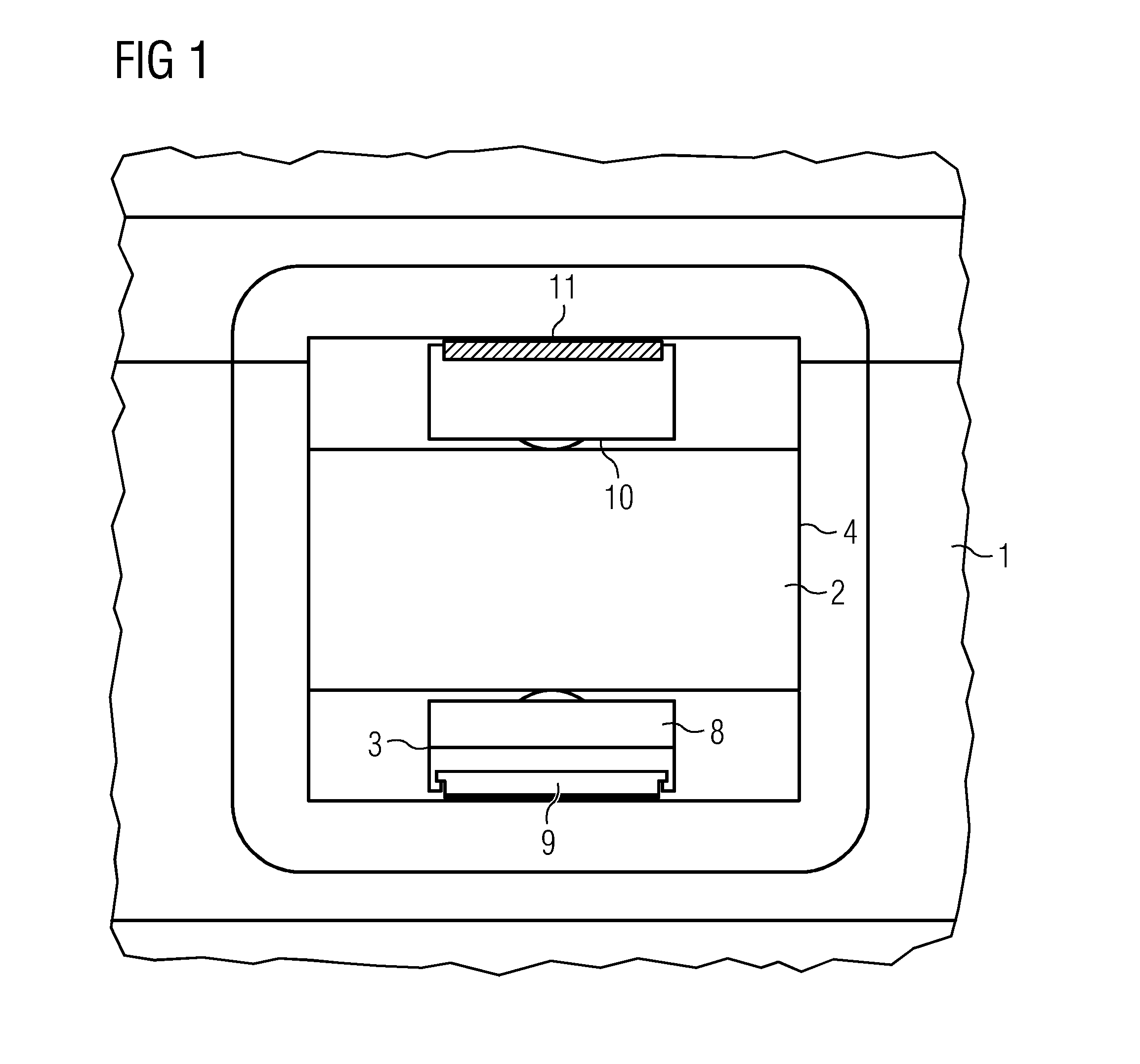
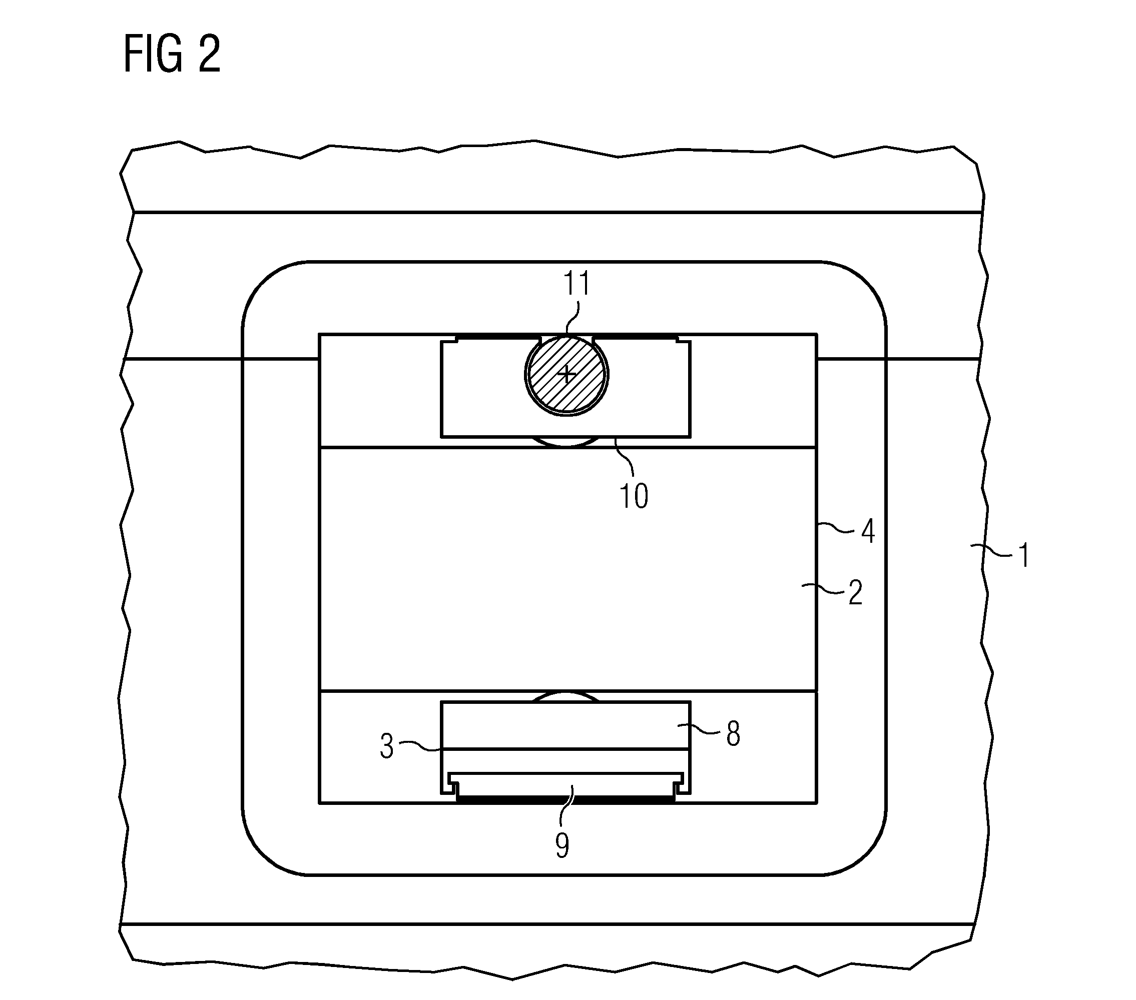
[0072]FIG. 2 shows the sliding bearing.

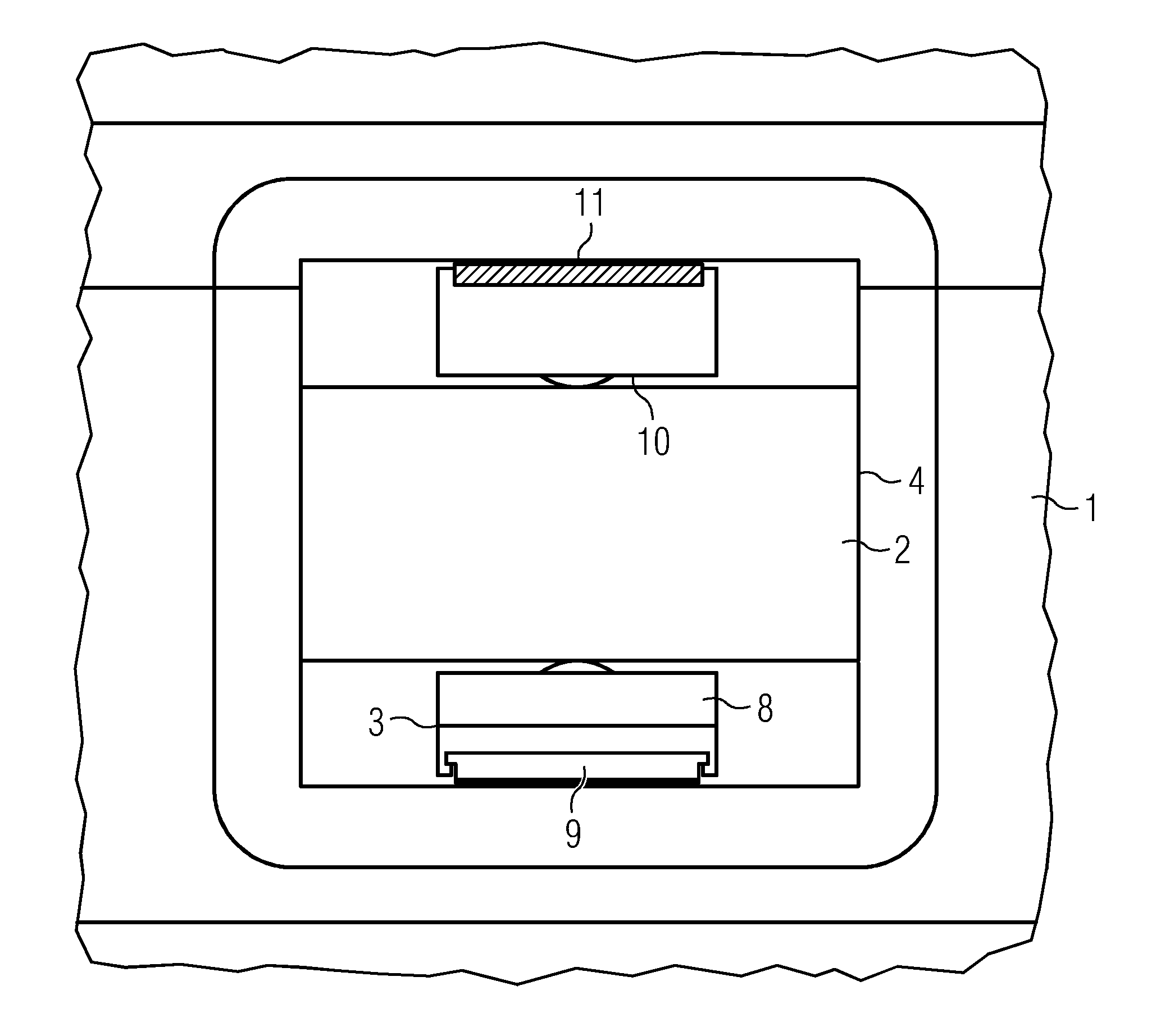
[0073]FIG. 2 shows an opening 4 in a first bearing shell 1. Through the opening 4 a second bearing shell 2 is visible. A bearing pad 3 comprising a pad carrier 8 and a liner 9 is attached to the second bearing shell 2.

[0074]A machining element 10 comprising a machining surface 11 is arranged between the first bearing shell 1 and the second bearing shell 2. The machining element 10 is attached to the second bearing shell 2.

[0075]The machining surface 11 is sliding along the sliding surface of the first bearing shell 1 when the bearing shells are rotating in respect to each other. The machining surface 11 is then treating the sliding surface of the first bearing shell 1.

third embodiment

[0076]FIG. 3 shows the sliding bearing.

[0077]FIG. 3 shows an opening 4 in a first bearing shell 1 of a sliding bearing. Two pad carriers 8 are visible. During normal operation the pad carriers 8 hold liners 9 that comprise a surface that slides along the sliding surface of the first bearing shell 1 during operation of the baring.

[0078]The liners 9 of the pad carriers are exchanged by liners with a machining property 12. These liners treat the sliding surface of the first bearing shell, when the first and the second bearing shell are rotated in respect to each other. The liners 12 can be exchanged through the opening 4.

[0079]FIG. 4 shows a detail of the third embodiment of the sliding bearing.

[0080]FIG. 4 shows an opening 4 in a first bearing shell 1. Three bearing pads 3 are visible through the opening 4. Two of the bearing pads 3 comprise a pad carrier 8 and liners 9. The third pad carrier is equipped with a liner 12 with a surface with a machining property 12. This third liner is ...


PUM

PropertyMeasurementUnit
diameteraaaaaaaaaa
diameteraaaaaaaaaa
thicknessaaaaaaaaaa

Abstract

A sliding bearing of a wind turbine and a method to perform a service at a sliding bearing are proposed. The sliding bearing has a first bearing shell and a second bearing shell and a plurality of bearing pads arranged between the first bearing shell and the second bearing shell. The bearing pads are connected to the second bearing shell and the first bearing shell has a sliding surface that is prepared and arranged so that the bearing pads can slide along the sliding surface when the bearing shells are moved in respect to each other. A machining element is arranged between the first bearing shell and the second bearing shell to treat the sliding surface of the first bearing shell.

Description

CROSS REFERENCE TO RELATED APPLICATIONS[0001]The present application claims priority to European Patent Office application No. 12185642.1 EP filed Sep. 24, 2012, the entire content of which is hereby incorporated herein by reference.FIELD OF INVENTION[0002]The invention relates to a sliding bearing and a method to perform a service at a sliding bearing.BACKGROUND OF INVENTION[0003]A wind turbine transfers the energy of moving air into electrical energy. The moving air accelerates the rotor of the wind turbine. The rotation of the rotor is transferred to an electrical generator. The electrical generator transforms the rotational energy into electrical energy.[0004]In the last years the concept of a direct driven wind turbine was established. In a direct driven wind turbine the rotational energy of the rotor is transferred to the generator directly without the use of a gearbox.[0005]In a direct driven wind turbine the rotor of the wind turbine is directly connected to the rotor of the...

Claims


Application Information

Patent Timeline
Patent Type & Authority Patents(United States)
IPC IPC(8): F16C17/00F03D11/00F16C17/03F16C17/02F16C33/24F16C43/02
CPCF16C2237/00F16C2360/31F16C2235/00F16C17/03F16C17/02F16C2300/14F03D11/0016F16C43/02Y02E10/722F03D11/0008Y10T29/53104Y10T29/49638F03D80/70F03D80/55Y02E10/72
Inventor PEDERSEN, BOTHOMSEN, KIM
Owner SIEMENS GAMESA RENEWABLE ENERGY AS
Why Eureka
Try Eureka