Flight planning methods and systems
a technology of flight planning and planning methods, applied in the field of flight planning methods and systems, can solve the problems of difficult identification of a base, affecting the ability of other bases to provide air traffic services, and heights and areas used to prevent reliable radar or radio coverage or air traffic services, etc., to achieve the effect of reducing the likelihood of actual conflicts between flying aircraft, facilitating and quickly understanding the user, and facilitating the contact of another user quickly and easily
- Summary
- Abstract
- Description
- Claims
- Application Information
AI Technical Summary
Benefits of technology
Problems solved by technology
Method used
Image

Examples
Embodiment Construction
[0001]Embodiments of the invention relate to flight planning methods and systems.
BACKGROUND TO EMBODIMENTS OF THE INVENTION
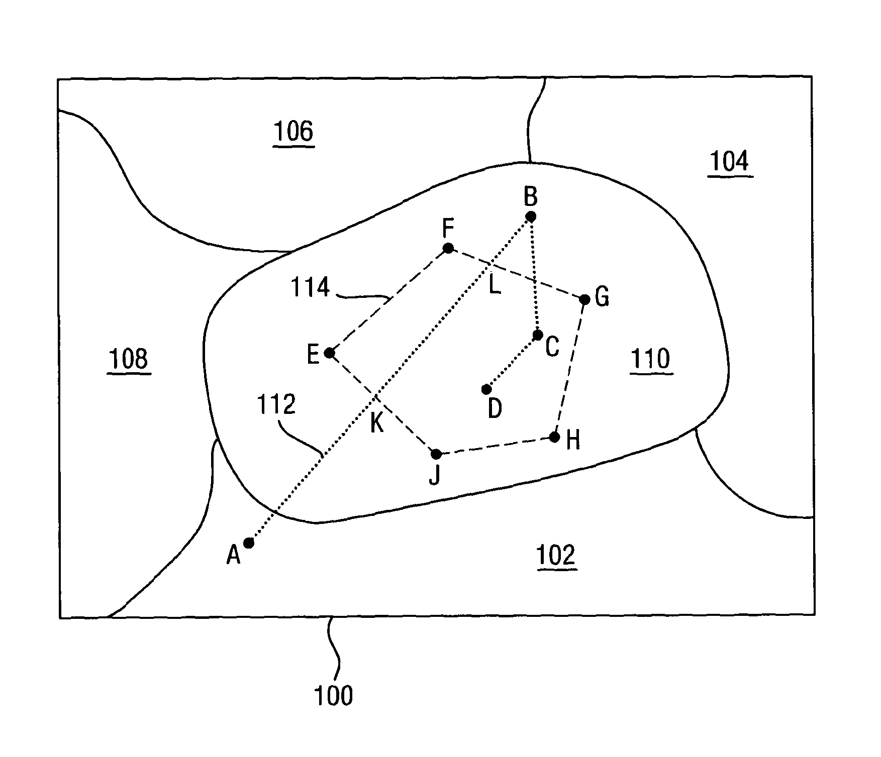
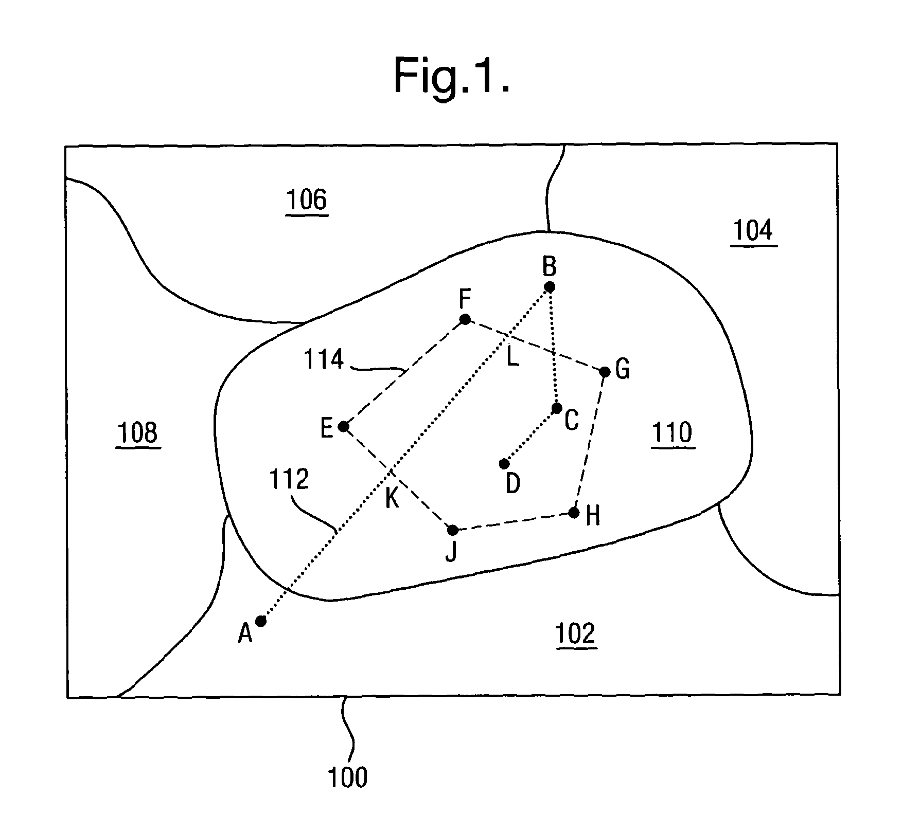
[0002]Fixed wing aircraft are judged to be low flying when they are less than 2000 feet from the ground. Light propeller driven aircraft and helicopters are judged to be low flying below 500 feet from the ground during the day and below 2000 feet at night. To manage low flying traffic density and increase flight safety, an authority divides the UK into defined Low Flying Areas (LFAs). The operating heights and areas used prevent reliable radar or radio coverage or provision of Air Traffic services. Users can book area entry / exit times and locations via a centralised booking cell, or in some cases a controlling authority. Booking requirements are designed to manage traffic density and provide an audit trail, for example in the case of low flying complaints or incidents. During the day, users are invariably unaware of any other booked users' detailed routes or tim...
PUM
 Abstract
Description
Claims
Application Information
 - R&D
- Intellectual Property
- Life Sciences
- Materials
- Tech Scout
- Unparalleled Data Quality
- Higher Quality Content
- 60% Fewer Hallucinations
Browse by: Latest US Patents, China's latest patents, Technical Efficacy Thesaurus, Application Domain, Technology Topic, Popular Technical Reports.
© 2025 PatSnap. All rights reserved.Legal|Privacy policy|Modern Slavery Act Transparency Statement|Sitemap|About US| Contact US: help@patsnap.com