
Image processor and image processing method having correcting unit performing correction based on correction parameters

a technology of image processing and correction parameters, applied in the direction of printing, other printing apparatus, etc., can solve the problems of printing images becoming more susceptible to density unevenness, inaccurate color, and color deviation of blue images expressed by overlapping

Inactive Publication Date: 2014-12-16
CANON KK
View PDF13 Cites 3 Cited by
  • Summary
  • Abstract
  • Description
  • Claims
  • Application Information

AI Technical Summary

Benefits of technology

[0010]The present invention has been devised in order to solve the above problems. Consequently, it is an object of the present invention to correct color unevenness which is caused by individual variation in ejection characteristics among nozzles for according to change over time and, even in the case, to curtail the processing time, expended print media, and ink volume used in the case of printing an image using a plurality of inks as possible.

Problems solved by technology

When such variation exists, printed images become more susceptible to density unevenness.
In other words, the above might cause inaccurate color, herein referred to as color deviation.
In other words, even if density unevenness in solid cyan images or solid magenta images is resolved by the head shading of the related art, the variation in ejection characteristics will still lead to color deviation in blue images expressed by overlapping combinations of these colors.
Furthermore, since the degree of color deviation differs among the regions printed by nozzles with different ejection characteristics, different shades of color are perceived in individual regions that should have the same coloring, which is noticed as color unevenness.

Method used


Image

  • Image processor and image processing method having correcting unit performing correction based on correction parameters
  • Image processor and image processing method having correcting unit performing correction based on correction parameters
  • Image processor and image processing method having correcting unit performing correction based on correction parameters

Examples


first embodiment

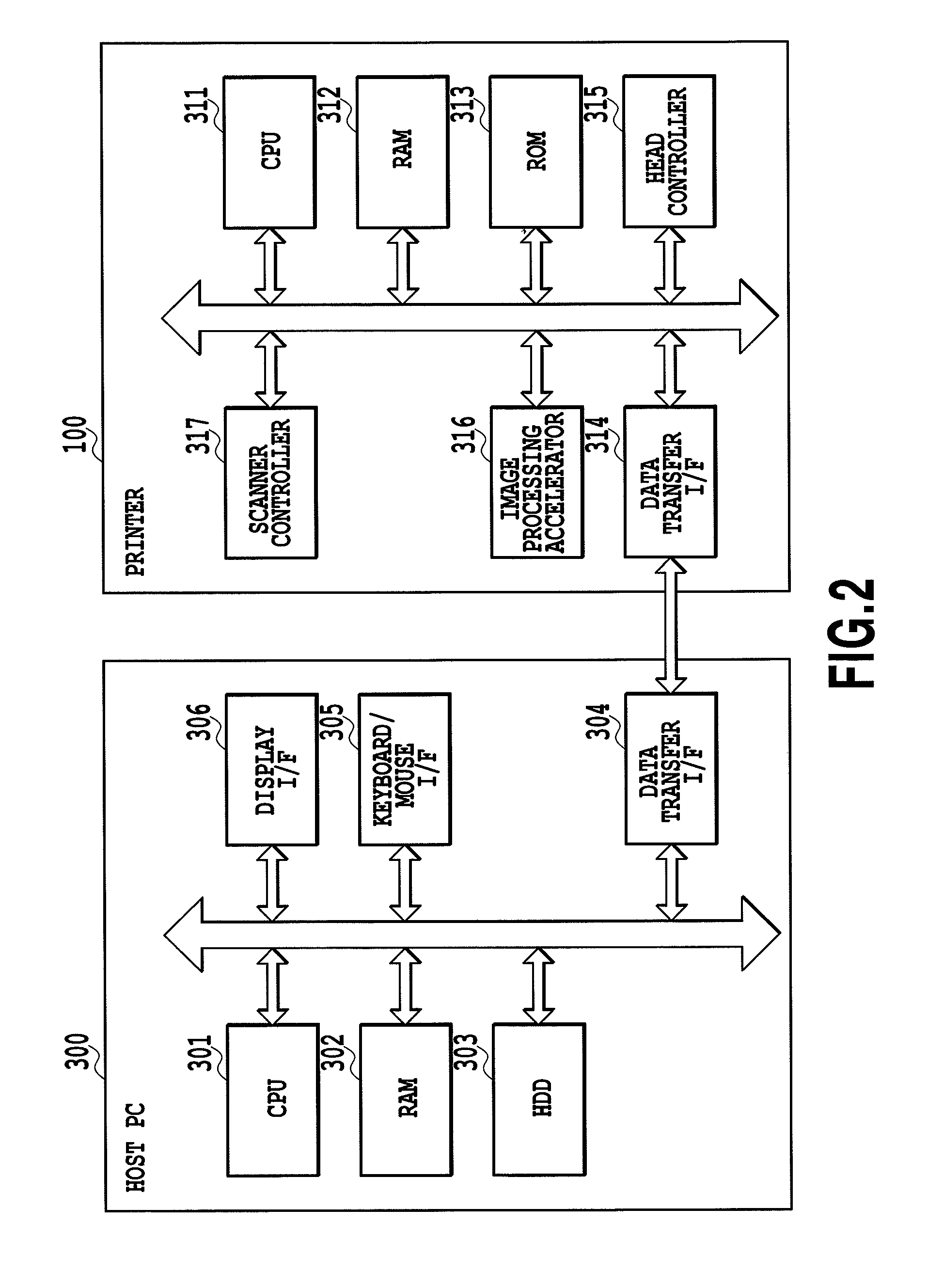
[0047]FIG. 4A is a block diagram illustrating a configuration of image processing operations executed by an inkjet printer in accordance with the first embodiment of the present invention. In other words, in the present embodiment, an image processor is realized by means of various components for executing the controls and processes of the printer 100 illustrated in FIG. 2. However, it should be appreciated that the application of the present invention is not limited to such an embodiment. For example, the image processor may also be realized in the PC 300 realized in FIG. 2. Alternatively, a part of the image processor may be realized in the PC 300, with the other parts realized in the printer 100.

[0048]As illustrated in FIG. 4A, the input unit 401 takes image data received from the host PC 300, and outputs the image data to the image processor 402. The image processor 402 includes an input color conversion processor 403, an MCS processor 404, an ink color conversion processor 405,...


PUM


Abstract

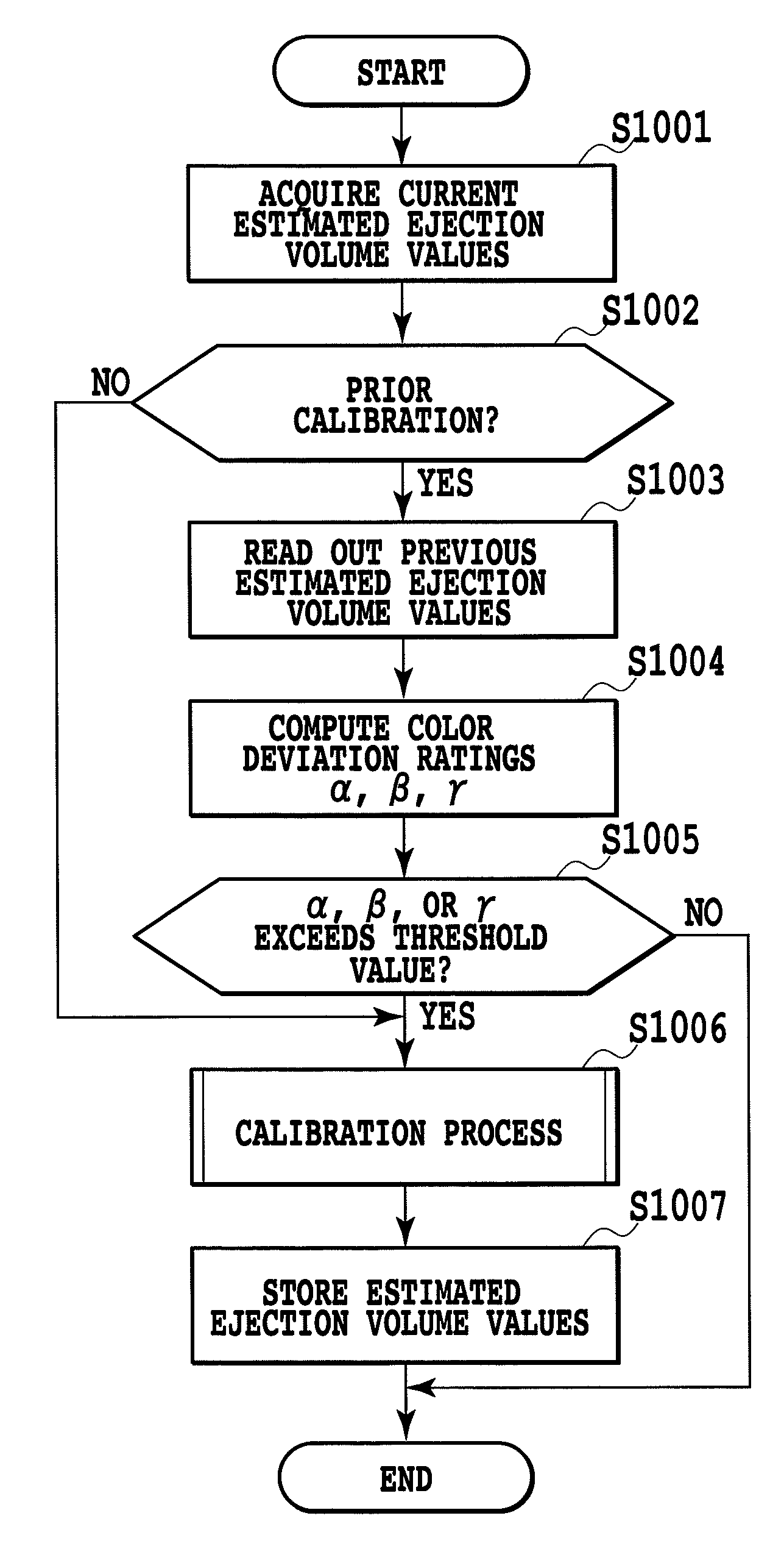
When printing an image using a plurality of inks, color unevenness caused by variations in ejection characteristics among nozzles is corrected at suitable timings in accordance with change in the color unevenness over time, and favorable image output without noticeably color unevenness is maintained. For this purpose, parameters are prepared, for colors formed by combinations of at least two colors of ink, the parameters being determined so as to reduce differences in coloration on a print medium caused by individual variations in the ejection characteristics of a plurality of nozzles. When printing, a first color signal included in individual pixels is corrected for a second color signal by using the parameters. Information regarding the ejection volume characteristics of a plurality of nozzles is acquired as appropriate, and by estimating changes in coloration from this information, suitable timings for overwriting such parameters are determined.

Description

BACKGROUND OF THE INVENTION[0001]1. Field of the Invention[0002]The present invention relates to an image processor and an image processing method. More particularly, the present invention relates to an image processor configured to decrease color unevenness caused by individual variations in the ejection characteristics of a plurality of nozzles that eject ink.[0003]2. Description of the Related Art[0004]In print heads used in inkjet printing apparatus, individual variations are sometimes exhibited in the ejection characteristics (i.e., the ejection volume and ejection direction, for example) of a plurality of nozzles, due to manufacturing errors and other factors. When such variation exists, printed images become more susceptible to density unevenness.[0005]In the related art, one established process for decreasing such density unevenness involves using head shading technology such as that disclosed in Japanese Patent Laid-Open No. H10-013674 (1998). Head shading is a technology t...

Claims


Application Information

Patent Timeline
Patent Type & Authority Patents(United States)
IPC IPC(8): B41J2/21B41J29/38
CPCB41J2/2139
Inventor YAMADA, AKITOSHIIGUCHI, RYOSUKEMIYAKE, NOBUTAKAIKEDA, TOHRUONO, MITSUHIROGOTO, FUMITAKAKAGAWA, HIDETSUGUISHIKAWA, TOMOKAZUNAKAGAWA, JUNICHISAITO, SENICHI
Owner CANON KK
Learn More