
Color unevenness correction device and color unevenness correction method

a color unevenness and correction device technology, applied in the direction of instruments, static indicating devices, etc., can solve the problems of color unevenness caused by display devices, write signals supplied to one color picture element do not have a desirable potential, and cannot ignore the impedance of the source line for both ends of the screen, etc., to achieve the effect of correcting color unevenness

Inactive Publication Date: 2017-07-27
MEGACHIPS
View PDF5 Cites 2 Cited by
  • Summary
  • Abstract
  • Description
  • Claims
  • Application Information

AI Technical Summary

Benefits of technology

The present invention provides a device and method to correct color unevenness in a time-division display caused by screen position. This ensures that the display looks good and is not affected by any color unevenness that might occur.

Problems solved by technology

Therefore, impedances of the source lines for the both end parts of the screen cannot be ignored.
Therefore, a phenomenon that the write signal supplied to one color picture element does not have a desirable potential occurs due to influence of the write signals supplied to other color picture elements.
Therefore, the display device cannot solve the problem that correct colors cannot be displayed depending on the screen position.
In the display device disclosed in WO 2012 / 157093, the influence of the write signals supplied to other color picture elements is not taken into account, and thus the color unevenness caused in the time-division display device cannot be solved.

Method used


Image

  • Color unevenness correction device and color unevenness correction method
  • Color unevenness correction device and color unevenness correction method
  • Color unevenness correction device and color unevenness correction method

Examples


first embodiment

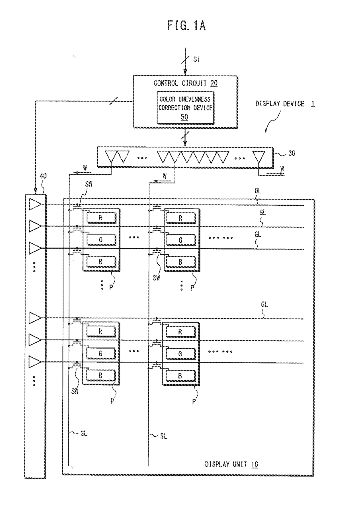
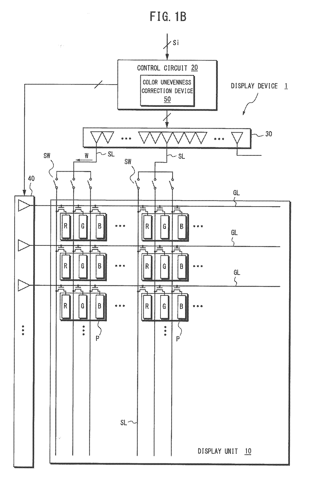
[0039]FIGS. 1A and 1B are block diagrams illustrating a display device in which a color unevenness correction device according to an embodiment of the present invention may be applied. As shown in FIGS. 1A and 1B, a display device 1 may include a display unit 10, a control circuit 20, and a plurality of source drivers 30 and a plurality of gate drivers 40 for driving the display unit 10 under the control by the control circuit 20.

[0040]As shown in FIG. 1A, the display unit 10 may include a screen (panel) including a plurality of pixels P arranged in a matrix in X-Y directions (i.e., horizontal and vertical directions). Each of the plurality of pixels P may include, for example, three types of color picture elements (sub-pixels), i.e., a red picture element R, a green picture element G, and a blue picture element B. In the present example, the display unit 10 may be configured such that one source driver 30 may drive the color picture elements composing the pixels P arranged in the v...

second embodiment

[0074]The present embodiment discloses a color unevenness correction device configured to use the write signals W for the color picture elements composing the pixels P of the same scan line to specify the correction amount α. In other words, for the color picture elements composing a pixel P(x, y) to be corrected adjacent to a pixel P(x, y-1) of the latest scan line, the color unevenness correction device of the present embodiment may be configured to use the write signals for the color picture elements composing the same pixel P(x, y) to specify the correction amount α, instead of using the write signals W for the adjacent color picture elements composing the pixel P(x, y-1) of the latest scan line.

[0075]FIG. 8 is a block diagram illustrating the color unevenness correction device according to an embodiment of the present invention.

[0076]As shown in FIG. 8, a color unevenness correction device 50′ of the present embodiment does not include the line buffer 52 for holding the write s...


PUM


Abstract

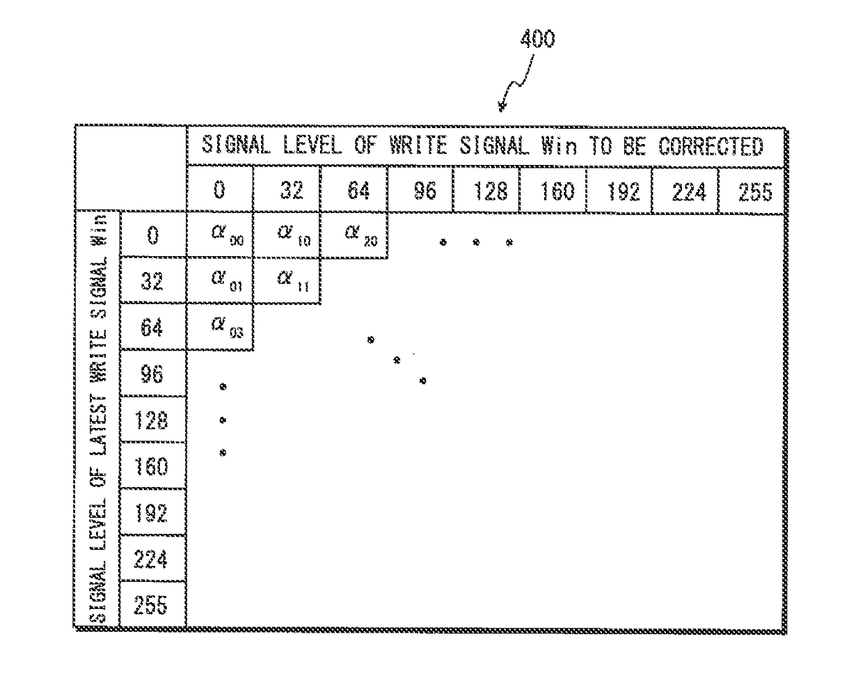
A color unevenness correction device is adapted to the display device that operates in accordance with the write signals supplied to a plurality of color picture elements composing one pixel in a time-division manner through a common signal line. The color unevenness correction device specifies a correction amount based on a first write signal for a first color picture element composing the one pixel and a second write signal for a second color picture element other than the first color picture element composing the pixel and corrects the second write signal in accordance with the correction amount.

Description

BACKGROUND OF THE INVENTION[0001]Field of the Invention[0002]The present invention relates to color unevenness correction devices and methods, and particularly, to a color unevenness correction device and method for a display device (liquid crystal panel) of a time-sharing signal supply system.[0003]Description of the Related Art[0004]Conventionally, a display device (hereinafter, “time-division display device”), in which a single source driver supplies write signals in a time-division manner to, for example, a red picture element R, a green picture element G, and a blue picture element B composing one pixel, is known. In such time-division devices, the number of source drivers can be reduced to ⅓, compared to a display device that supplies write signals by providing an individual source driver for each color picture element. Advantageously, the time-division device allows the number of connection terminals to be reduced and thus achieves low production costs.[0005]In such time-divi...

Claims


Application Information

Patent Timeline
Patent Type & Authority Applications(United States)
IPC IPC(8): G09G3/20G09G3/36
CPCG09G3/2003G09G2310/08G09G2320/0242G09G3/3607G09G3/3611G09G2300/0452G09G3/2059G09G2320/0285G09G2340/16
Inventor OCHIAI, KAZUNORI
Owner MEGACHIPS
Learn More