Eureka AIR delivers breakthrough ideas for toughest innovation challenges, trusted by R&D personnel around the world.

Starting method for rotating machine and starting method for wind turbine generator

a technology of rotating machines and starting methods, which is applied in the direction of turbines, machines/engines, sliding contact bearings, etc., can solve the problems of equipment malfunction or leakage of lubricant, deterioration of the circularity of lubricant, and lubricant cooling of a lubrication system

Active Publication Date: 2014-11-18
MITSUBISHI HEAVY IND LTD
View PDF34 Cites 12 Cited by
  • Summary
  • Abstract
  • Description
  • Claims
  • Application Information

AI Technical Summary

Benefits of technology

[0010]It is therefore an object of the present invention to provide a method of starting a rotating machine, such as a wind turbine generator, disposed in a cold environment, which method can deal with a problem of deterioration in lubricant discharge efficiency due to cooling of a main bearing.

Problems solved by technology

One of issues necessary to be considered in constructing a wind turbine generator in a cold environment is that lubricant of a lubrication system is cooled when the wind turbine generator stops operating.
When the lubricant is cooled after the wind turbine generator stops operating, the viscosity of the lubricant is increased, causing deterioration of the circularity of the lubricant.
When the viscosity of the lubricant is excessively increased, load is imposed on equipment (such as a lubricant pump) constituting the lubrication system and pipes, potentially causing equipment malfunction or leakage of the lubricant.
This problem is serious particularly when the wind turbine generator in an extremely cold environment is to be started.
According to study of the inventor of the present invention, however, the technique for supplying the heated lubricant is not always appropriate for a component, such as a main bearing, having a large heat capacity and a large contact area with the lubricant.
When the heated lubricant is supplied to the cooled main bearing, then the lubricant is instantly cooled to increase the viscosity of the lubricant, causing deterioration of the lubricant discharge efficiency.
When lubricant of an amount exceeding the amount of lubricant dischargeable from the main bearing is supplied to the main bearing, leakage of the lubricant may occur.
To provide a heater heating the main bearing may be an approach for avoiding the above-stated problem; however, the approach of providing the heater heating the main bearing suffers from problems of a larger heat capacity of the main bearing of the wind turbine generator, and inevitable heat transmission to the nacelle base, which has a large heat capacity.
To heat the main bearing to a necessary temperature using the heater, it is necessary to provide a heater having a considerably large heating capacity and a considerably long heating time is required.
In these circumstances, it may be impractical to heat the main bearing using a heater.
The above-described problem also applies to other rotating machines including a bearing with a large heat capacity (for example, shield machines, printing machines and industrial machines such as power generator turbines).

Method used


Image

  • Starting method for rotating machine and starting method for wind turbine generator
  • Starting method for rotating machine and starting method for wind turbine generator
  • Starting method for rotating machine and starting method for wind turbine generator

Examples


Embodiment Construction

[0027]FIG. 1 is a side view showing a configuration of a wind turbine generator 1 in one embodiment of the present invention. The wind turbine generator 1 includes a tower 2 provided upright to a base 6, a nacelle 3 disposed on the top of the tower 2, a rotor head 4 provided rotatably to the nacelle 3, and wind turbine blades 5 attached to the rotor head 4. The rotor head 4 and the wind turbine blades 5 constitute a wind turbine rotor.

[0028]As shown in FIG. 2, the rotor head 4 is connected to one end of a main shaft 11 which transmits power from the wind turbine rotor to a speed-up gear 13, and the main shaft 11 is rotatably supported by a main shaft bearing 12 which is a rolling bearing. The other end of the main shaft 11 is connected to the input shaft of the speed-up gear 13. The output shaft of the speed-up gear 13 is connected to the rotor of a generator 14. When the rotor head 4 rotates by wind force, the rotation is transmitted to the rotor of the generator 14 to drive the ge...


PUM


Abstract

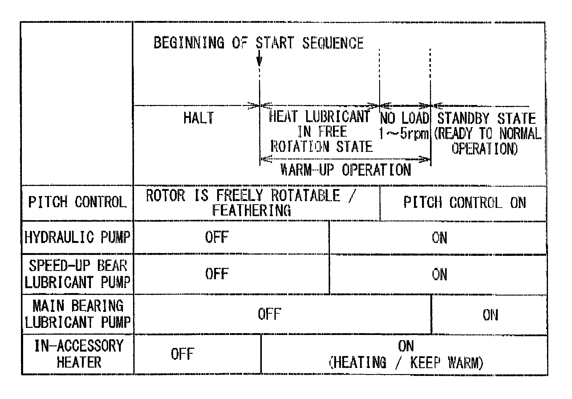
A starting method is provided for a rotating machine which includes a main shaft, a main bearing rotatably supporting the main shaft and a main bearing lubricant pump circulating lubricant through the main bearing. The starting method includes steps of: rotating the main shaft to raise a temperature of the main bearing in a state in which the main bearing lubricant pump is not operated; and operating the main bearing lubricant pump to start supplying the lubricant to the main bearing after the step of raising the temperature of the main bearing.

Description

RELATED APPLICATIONS[0001]The present application is a continuation Application of PCT / JP2010 / 052543 filed on Feb. 19, 2010, and the disclosure of which is hereby incorporated by reference herein in its entirety.BACKGROUND OF THE INVENTION[0002]1. Field of the Invention[0003]The present invention relates to a method of starting a rotating machine, and more particularly, to a method of starting a rotating machine, such as a wind turbine generator, disposed in a cold environment.[0004]2. Description of the Related Art[0005]Wind turbine generators are increasingly constructed across the globe in favor of promotion of use of renewable energy. It is therefore demanded to construct wind turbine generators even in a cold environment.[0006]One of issues necessary to be considered in constructing a wind turbine generator in a cold environment is that lubricant of a lubrication system is cooled when the wind turbine generator stops operating. When the lubricant is cooled after the wind turbin...

Claims


Application Information

Patent Timeline
Patent Type & Authority Patents(United States)
IPC IPC(8): F16C21/00F01M5/00F16C43/00F16N39/04F16N1/00F16N29/02F03D11/00F03D7/02F16C17/00
CPCF16N2210/14F16N2210/025F03D7/026F16N39/04F16N2270/20F03D11/0008F16N2270/56F16N29/02Y02E10/726F05B2260/20F16N2250/08F16N39/02Y02E10/723Y02E10/722F03D80/70F16C2360/31Y02E10/72F16C33/6659
Inventor TAKAYANAGI, KAZUFUMI
Owner MITSUBISHI HEAVY IND LTD
Why Eureka
Eureka Blog
Learn More