Button key assembly and electronic apparatus that employs the button key assembly

a technology of electronic devices and button keys, applied in the direction of pulse techniques, emergency actuators, keyboard-like device coding, etc., can solve problems such as the impairing of the operability of the keyboard, and achieve the effect of good operability

Inactive Publication Date: 2014-11-04
OKI DATA CORP
View PDF8 Cites 2 Cited by
  • Summary
  • Abstract
  • Description
  • Claims
  • Application Information

AI Technical Summary

Benefits of technology

[0006]An objection of the present invention is to solve the aforementioned drawbacks, and to provide a keyboard that offers good operability.
[0007]Another object of the invention is to provide a keyboard in which adjacent keys are spaced apart by as short a distance as possible so that the operability of the keyboard is least affected and excellent operability is obtained.

Problems solved by technology

This gap may cause the keys to rattle after they have been assembled as a key board, impairing the operability of the keyboard.

Method used


Image

  • Button key assembly and electronic apparatus that employs the button key assembly
  • Button key assembly and electronic apparatus that employs the button key assembly
  • Button key assembly and electronic apparatus that employs the button key assembly

Examples


first embodiment

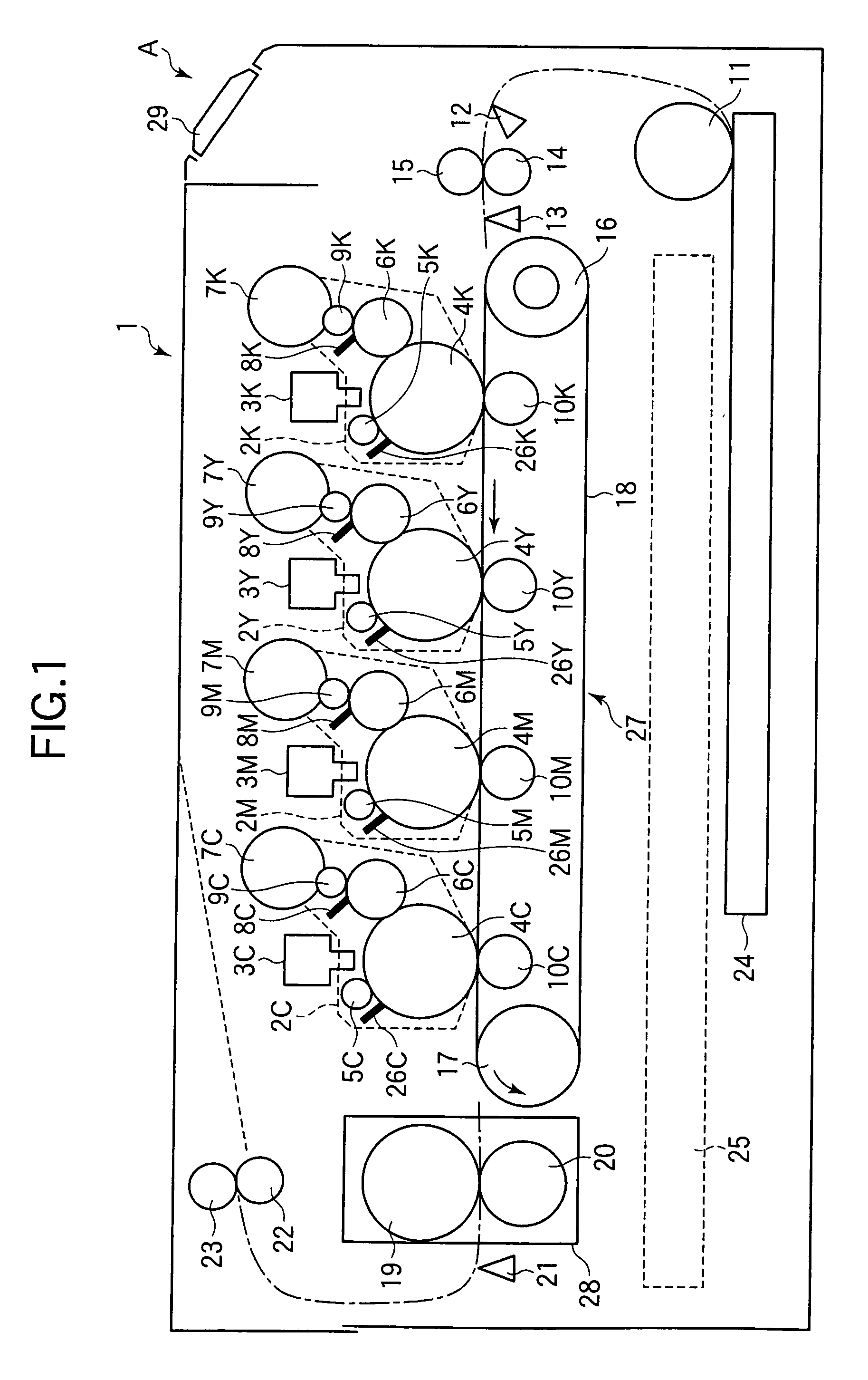
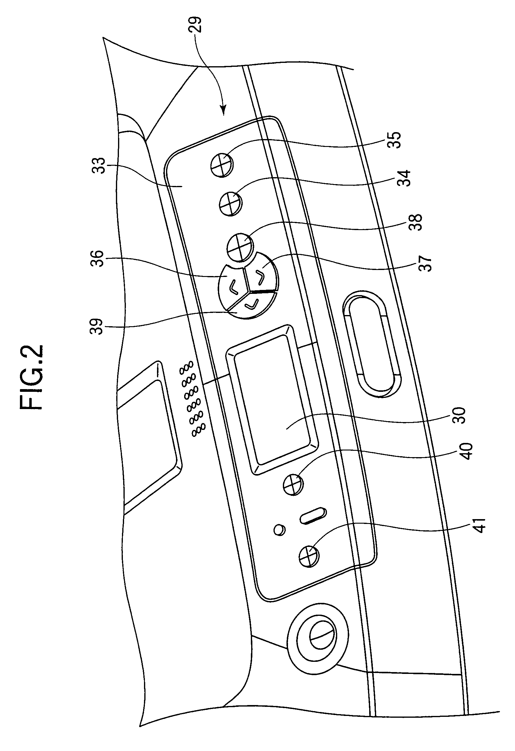
[0033]FIG. 1 illustrates a pertinent portion of an image forming apparatus 1 that employs an operator panel 29 of a first embodiment.

[0034]Referring to FIG. 1, print engines 2K, 2Y, 2M, and 2C are aligned in this order in a direction of travel of paper. Transfer rollers 10K, 10Y, 10M, and 10C are disposed to face corresponding print engines 2K, 2Y, 2M, and 2C, respectively, such that an endless type transport belt 18 is sandwiched between the print engines 2K, 2Y, 2M, and 2C and the corresponding transfer rollers 10K, 10Y, 10M, and 10C. The transport belt 18 is disposed about a drive roller 17 and a driven roller 16. The transfer belt 18, drive roller 17, and driven roller 16 cooperate with one another to form a transfer unit 27. A paper cassette 24 holds a stack of paper therein. A feed roller 11 cooperates with a separator (not shown) to feed the top page of the stack of paper from the paper cassette 24. An entrance sensor 12 and a write sensor 13 are located upstream of transport...

second embodiment

[0068]FIG. 13 is a front view illustrating an operator panel 129 of a second embodiment.

[0069]FIG. 14 is a cross-sectional view taken along a line B-B of FIG. 13.

[0070]FIG. 15 is a partial expanded view of an area depicted at 500 shown in FIG. 13.

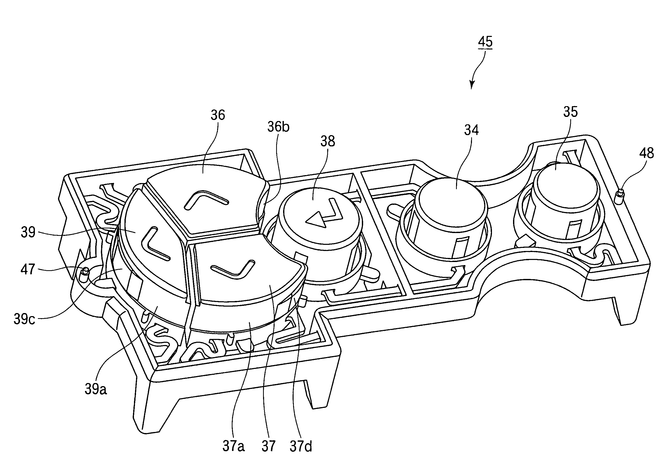
[0071]FIG. 16 is a perspective view of a button key assembly 145 as seen obliquely from above.

[0072]FIG. 17 is a perspective view of the button key assembly 145 as seen obliquely from under.

[0073]Referring to FIG. 13, the operator panel 129 differs from the operator panel 29 in the configuration of an upper menu key 136, a lower menu key 137, and a back key 139. Elements similar to those in the first embodiment have been given the same reference numerals and their description is omitted. The configuration of the image forming apparatus 1 of the second embodiment is the same as that of the image forming apparatus 1 of the first embodiment except for the operator panel 129. Thus, the second embodiment will be described with reference to FIG. ...


PUM


Abstract

Button keys, resilient supports and a frame are molded in one piece such that the button keys are resiliently movable and are spaced apart by a gap. Each of the button keys includes an engagement portion. A case includes a button hole formed therein. The case is assembled to the frame such that the button keys are received in the button hole. After the case has been assembled to the frame such that the plurality of adjacent button keys are received in the button hole and such that the engagement portion abuts a perimeter portion of the button hole, the second gap being smaller than the first gap.

Description

BACKGROUND OF THE INVENTION[0001]1. Field of the Invention[0002]The present invention relates to a button key assembly of an operator panel incorporated in a variety of electronic equipment including copying machines, facsimile machines, personal computers, telephones, and gaming machines.[0003]2. Description of the Related Art[0004]Conventional electronic apparatuses include an operator panel that employs a variety of operational keys that allow a user to operate the electronic apparatus. Such apparatuses include copying machines, facsimile machines, personal computers, telephones, and gaming machines. An operator panel includes a variety of operational keys such as selection keys for selecting a variety of functions such as “ENTER” and “RETURN” for confirming the selection, and “BACK KEY” for returning to the immediately previous state. These keys are commonly arranged closely for the purposes of functionality and design.[0005]If a plurality of operational keys is to be closely lo...

Claims


Application Information

Patent Timeline
Patent Type & Authority Patents(United States)
IPC IPC(8): H01H13/7057H01H13/88H01H9/26H01H13/76H01H13/72
CPCH01H2223/0345H01H2221/054H01H13/7057H01H2221/044H01H13/88H01H2221/062H01H2221/074
Inventor HARUYAMA, MASAHIRO
Owner OKI DATA CORP
Why Eureka
Try Eureka