Vacuum element and method for producing the same

a vacuum element and vacuum technology, applied in solar ray transmission and preventing heat radiation, pv power plants, sustainable buildings, etc., can solve the problems of time-consuming and cumbersome tasks, cumbersome and deficient, and achieve enhanced energy yield, secure connection, and the effect of avoiding or reducing disadvantageous reflections

Inactive Publication Date: 2014-11-04
LISEC AUSTRIA
View PDF14 Cites 6 Cited by
  • Summary
  • Abstract
  • Description
  • Claims
  • Application Information

AI Technical Summary

Benefits of technology

[0008]With the method according to the invention, it is also possible to achieve a secure connection between the individual components of the vacuum element according to the invention by virtue of the fact that between the flat components, a material is introduced that secures these components (fittings) that are bound together and are incorporated in the interior of the vacuum element. Thus, for example, on the inside of at least one of the flat components (in particular glass panes), films, preferably composite films, can be provided. Such composite films, for example single-layer films made of polyvinyl butyral (PVB), have the advantage that the entrance of light, which strikes the solar module (or solar collector) arranged in the interior of the vacuum element, takes place without a transition from an optically thicker medium (e.g., glass) to an optically thinner medium (e.g., air), and reflection, in particular total reflection, is avoided, so that the energy yield is enhanced, since no losses by reflected light occur. Disadvantageous reflections can also be reduced or avoided by the anti-reflective layers applied on the inside of the first component.

Problems solved by technology

This is a time-intensive and cumbersome task, in particular since the after-the-fact sealing of the opening through which the vacuum has been applied is cumbersome and deficient.

Method used


Image

  • Vacuum element and method for producing the same
  • Vacuum element and method for producing the same
  • Vacuum element and method for producing the same

Examples


Embodiment Construction

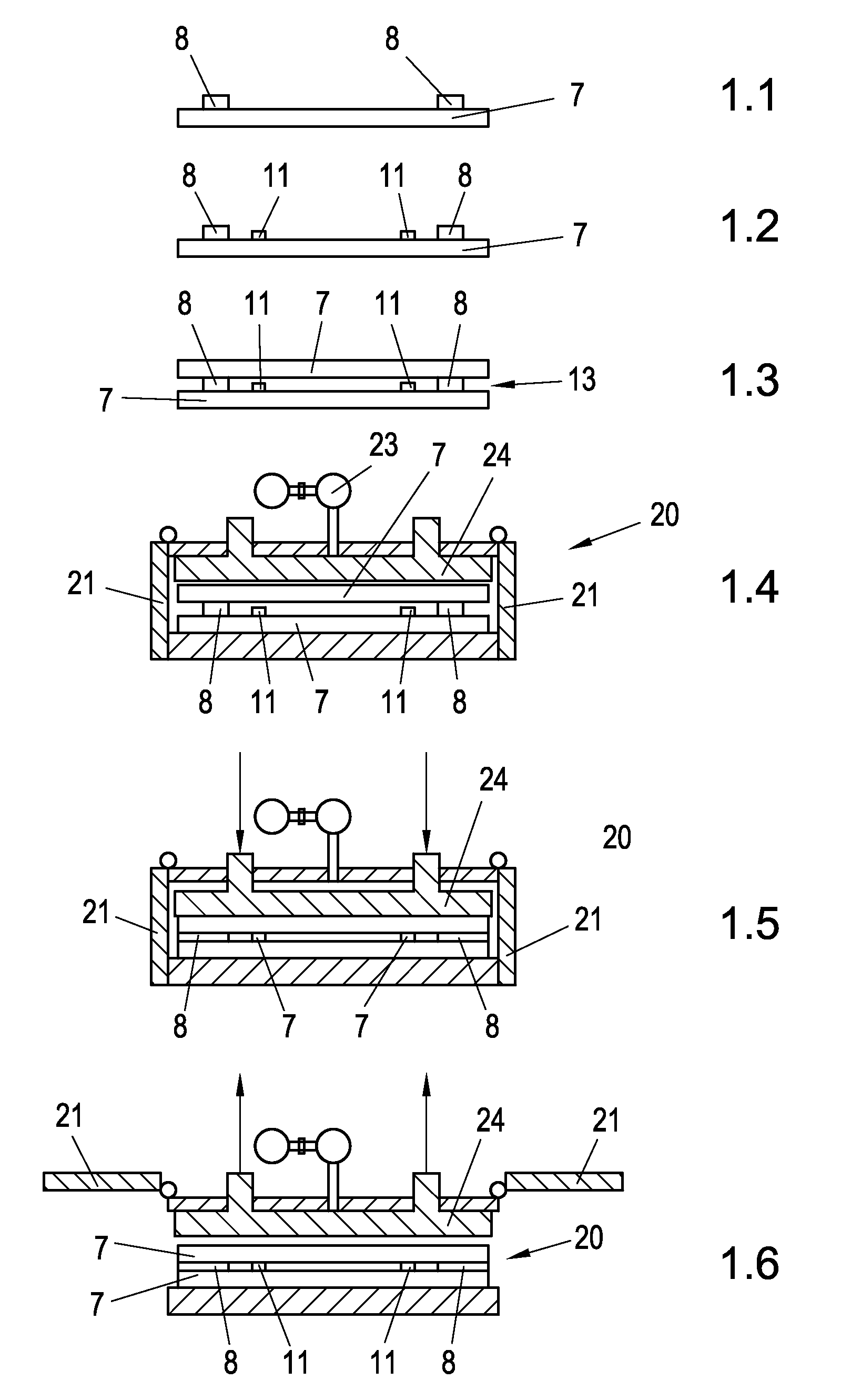
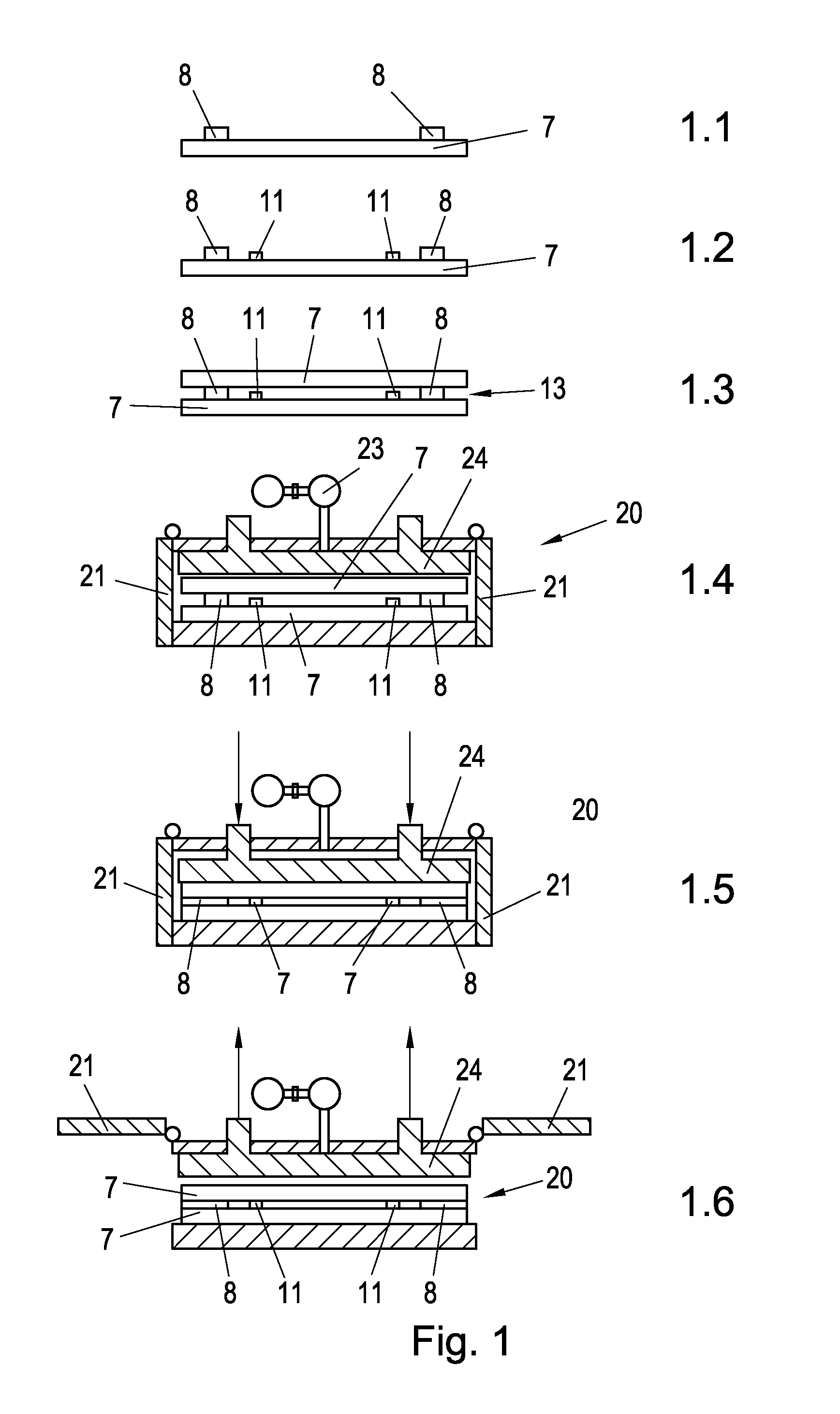
[0020]The method shown as an example in FIG. 1 proceeds as follows:

1. Applying Diffusion-Tight Edge Coating Material (Bead 8)

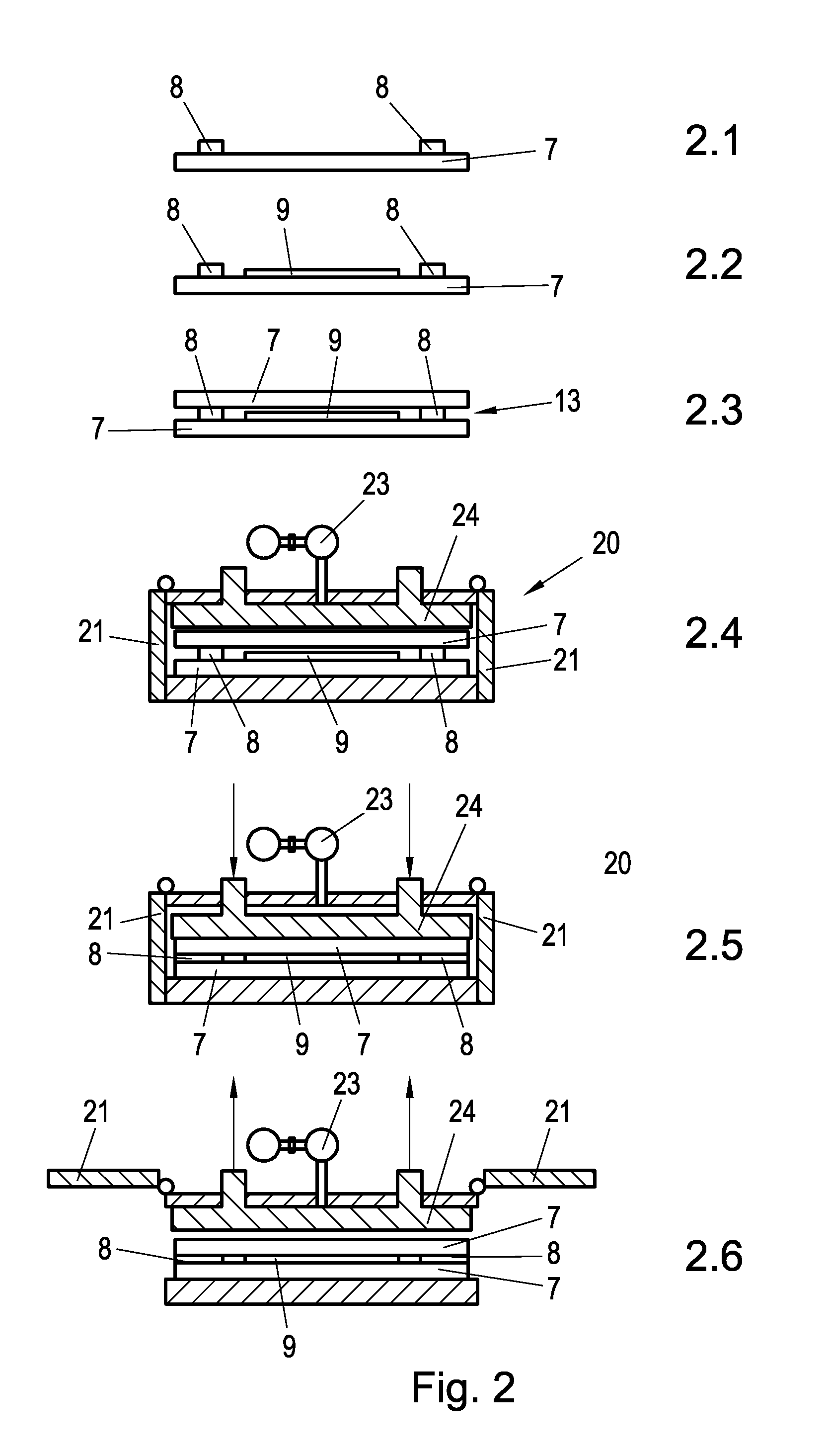
[0021]A bead 8 that consists of, e.g., diffusion-tight sealing material is applied on all four sides on the edge on the surface of glass pane 7 surface (first component) in a vertical or horizontal application system. Contours or inside cutaways can also be surrounded with a bead 8 with this application system.[0022]1.1 Edge coating material 8 is applied as a bead on a glass pane 7 (first component) (FIG. 1).[0023]1.2 Edge coating material 8 is applied on an already pre-laminated 9 glass pane 7 (FIG. 2).[0024]1.3 Edge coating material 8 is applied on a coated glass pane 107 (for the production of thin-layer PV modules) (FIG. 3).

2. Fittings

[0025]Depending on the vacuum element (modular design) to be produced, various inserts (fittings) are inserted into the sealed pane manually or automatically.[0026]2.1 For vacuum glass production (empty vacuum element, i.e., ...


PUM

PropertyMeasurementUnit
pressureaaaaaaaaaa
heightaaaaaaaaaa
thicknessaaaaaaaaaa

Abstract

For the production of vacuum elements, which optionally contain fittings in the form of at least one solar module (photovoltaic element) and/or a solar collector or a display element, negative pressure is produced in a space between two flat components, in particular translucent or transparent plates, such as glass panes that are bound together via a bead made of sealing material, such that an arrangement that consists of a first component provided with a bead and at a distance therefrom but parallel to the second component arranged therein, is introduced into a vacuum chamber and pressed under vacuum. In this case, an elevated temperature also optionally can be applied to laminate films provided between the components with the components and optionally present fittings.

Description

BACKGROUND OF THE INVENTION[0001]The invention relates to a vacuum element with the below features that is aimed at the element, on the one hand, and a method for producing such elements with the below features that is aimed at the method, on the other hand.DESCRIPTION OF THE RELATED ART[0002]When producing vacuum elements of the generic type, in most cases the procedure is that air is suctioned off from the interior space of the vacuum element via an opening in the edge seal between flat components.[0003]This is a time-intensive and cumbersome task, in particular since the after-the-fact sealing of the opening through which the vacuum has been applied is cumbersome and deficient.SUMMARY OF THE INVENTION[0004]The object of the invention is to introduce a vacuum element of the above-mentioned type and a method for producing the same.[0005]By the mode of operation that is proposed according to the invention, on the one hand, and with the design of the vacuum element that is proposed a...

Claims


Application Information

Patent Timeline
Patent Type & Authority Patents(United States)
IPC IPC(8): E06B3/677H01L31/042H01L31/048F24J2/50
CPCF24J2/507Y02B10/22Y02E10/50E06B3/6775H01J2209/26H01L31/048Y02E10/40Y02B10/10Y10T29/49355F24S80/54Y02B10/20E06B3/677
Inventor MADER, LEOPOLD
Owner LISEC AUSTRIA
Why Eureka
Try Eureka