
Power plug

a power converter and plug-in technology, applied in the field of plug-in, can solve the problems of inconvenient user and general only applicable plug-in of the power converter

Active Publication Date: 2014-11-04
WELL SHIN TECH
View PDF10 Cites 8 Cited by
  • Summary
  • Abstract
  • Description
  • Claims
  • Application Information

AI Technical Summary

Benefits of technology

The power plug described in this patent allows for easy conversion between US and Australian standards by rotating a ring to push a sliding strip, which then drives the plug pins to rotate. This makes it simple to connect electrical devices from different countries.

Problems solved by technology

However, the plug of the power converter generally only applies to a kind of wall socket.
It is quite inconvenient for user.

Method used


Image

  • Power plug
  • Power plug
  • Power plug

Examples


Embodiment Construction

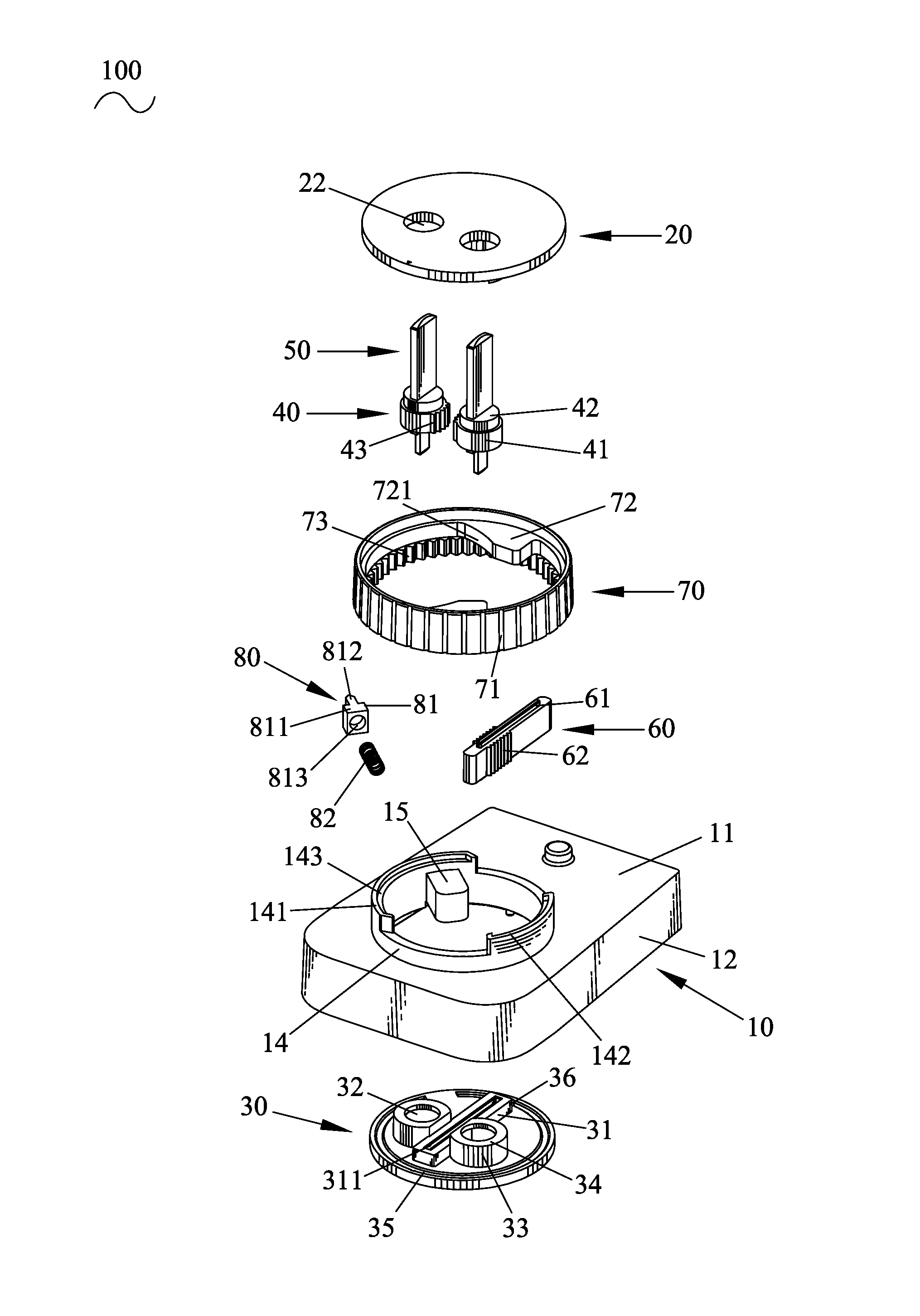
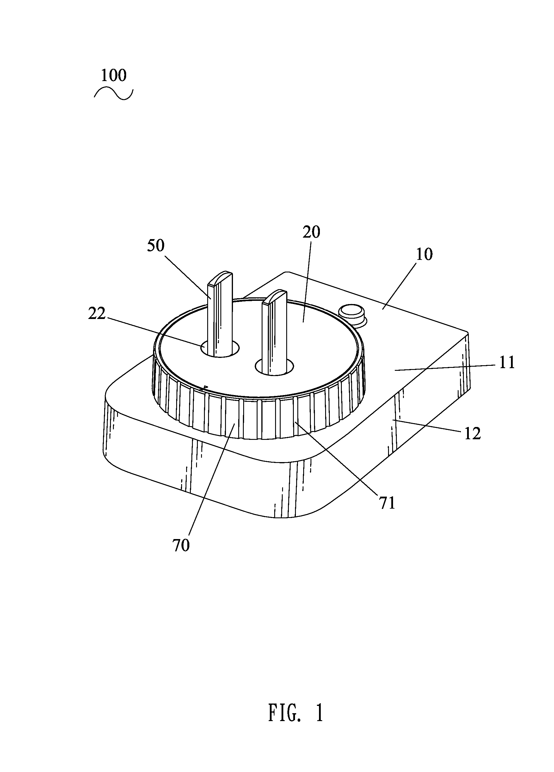
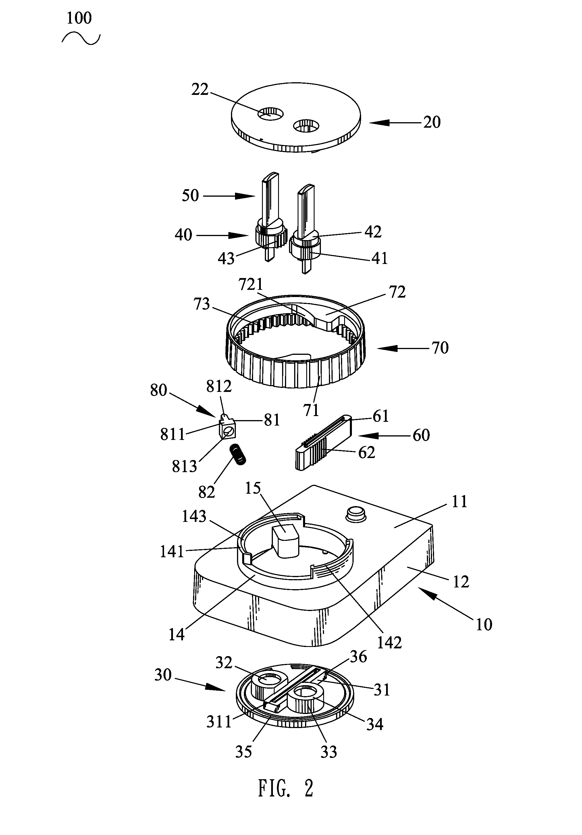
[0015]Referring to the drawings in greater detail, and first to FIG. 1 and FIG. 2, an embodiment of the present invention is embodied in a power plug 100. The power plug 100 includes an insulating housing 10, a top cover 20, a bottom cover 30, a pair of rotating axles 40, a pair of plug pins 50, a sliding strip 60, a rotating ring 70 and a braking apparatus 80.

[0016]With reference to FIGS. 2 to 5, the insulating housing 10 has a rectangle top plate 11 in which a receiving barrel 14 is vertically crossed, and a plurality of side plates 12 protruded downward from the edges of the top plate 11 and connected with one another. A pair of positioning pillars 13 is protruded downward at a bottom face of the top plate 11 and connects with the receiving barrel 14. A top edge of the receiving barrel 14 protrudes upward to form a blocking wall 142 and a fastening wall 141 apart from the blocking wall 142. The top faces of the fastening wall 141 and the blocking wall 142 each is concaved downwar...


PUM


Abstract

A power plug includes an insulating housing in which a receiving barrel is crossed, top and bottom covers covering top and bottom ends of the receiving barrel, a sliding strip slidably located between the top and bottom covers with serrated sliding teeth protruding on two opposite sides thereof, two rotating axles located at two sides of the sliding strip with rotating teeth protruding on two relative insides thereof and meshed with the sliding teeth, two plug pins vertically integrated in the rotating axles and a rotating ring sheathing outside the receiving barrel with two pushing blocks protruding at an inside wall thereof. The pushing blocks project into the receiving barrel and are against two ends of the sliding strip to push the sliding strip to slide by rotating the rotating ring so as to drive the rotating axles together with the plug pins to rotate relatively.

Description

BACKGROUND OF THE INVENTION[0001]1. Field of the Invention[0002]The present invention relates to a plug, and more particularly to a power plug.[0003]2. The Related Art[0004]With the progress of society, various kinds of electrical equipments have become an indispensable tool in people's daily life. Power converter as an electrical equipment, such as adapter of notebook and chargers of mobile phone and digital camera, is more and more widely used. The main function of the power converter is to convert AC (Alternating Current) to DC (Direct Current) to be used in DC equipments.[0005]The power converter electrically connects with a wall socket through a plug which is used to insert in the wall socket. However, the plug of the power converter generally only applies to a kind of wall socket. But the wall sockets in different countries often have different standards. In order to use the power converter in different countries, many different types of extra adapters matching with the differ...

Claims


Application Information

Patent Timeline
Patent Type & Authority Patents(United States)
IPC IPC(8): H01R29/00H01R27/00
CPCH01R27/00H01R2103/00H01R24/68
Inventor WU, JUI, HSIUNG
Owner WELL SHIN TECH
Learn More