
Directing vehicle into feasible region for autonomous and semi-autonomous parking

a technology for autonomous and semi-autonomous parking and directions of vehicles, which is applied in the direction of cycle equipment, transportation and packaging, instruments, etc., can solve the problems that the intended trajectory path may not be suitable for parallel parking of vehicles, and the task of parallel parking a vehicle between two vehicles is often a difficult task for drivers

Active Publication Date: 2014-10-14
GM GLOBAL TECH OPERATIONS LLC
View PDF29 Cites 20 Cited by
  • Summary
  • Abstract
  • Description
  • Claims
  • Application Information

AI Technical Summary

Benefits of technology

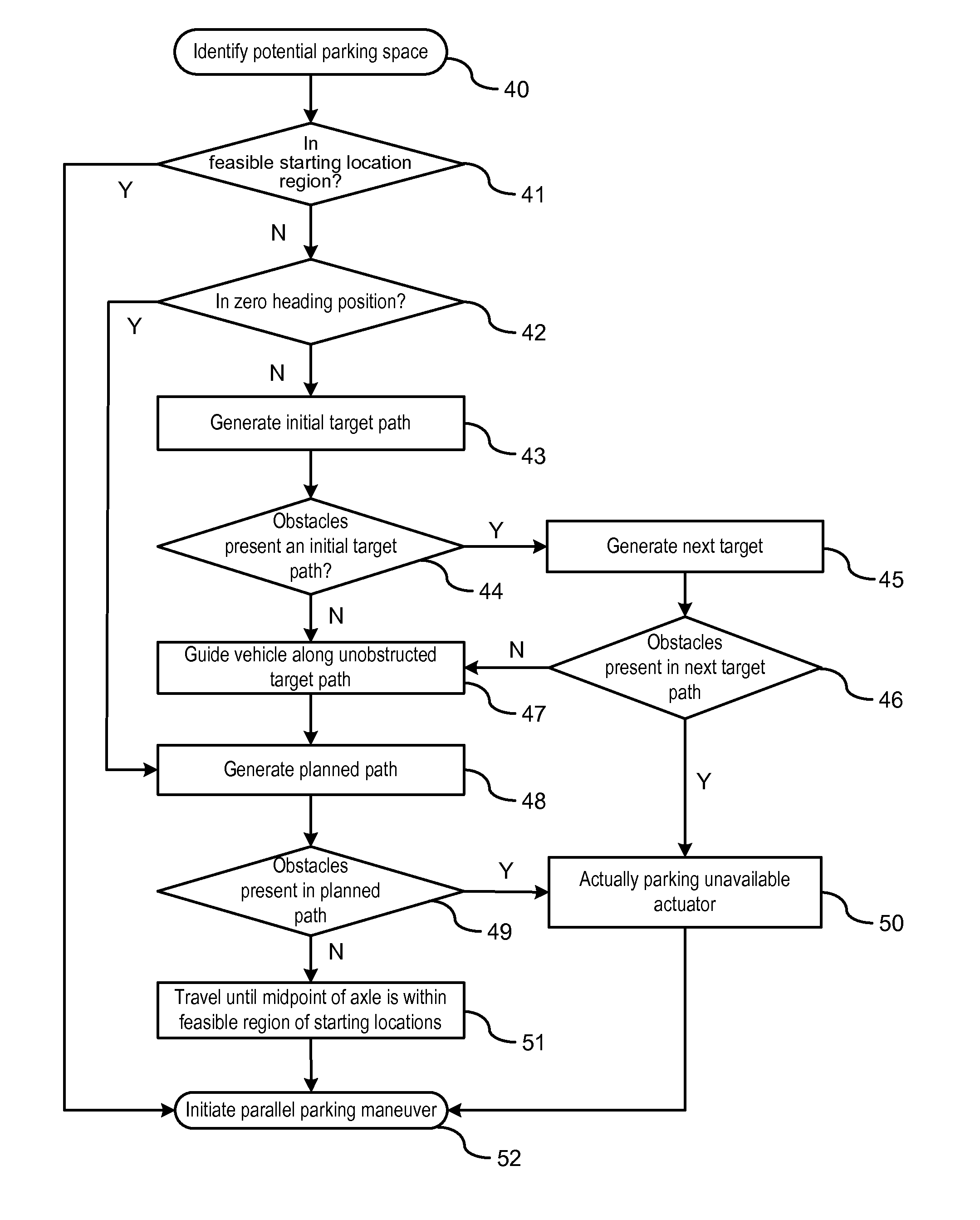
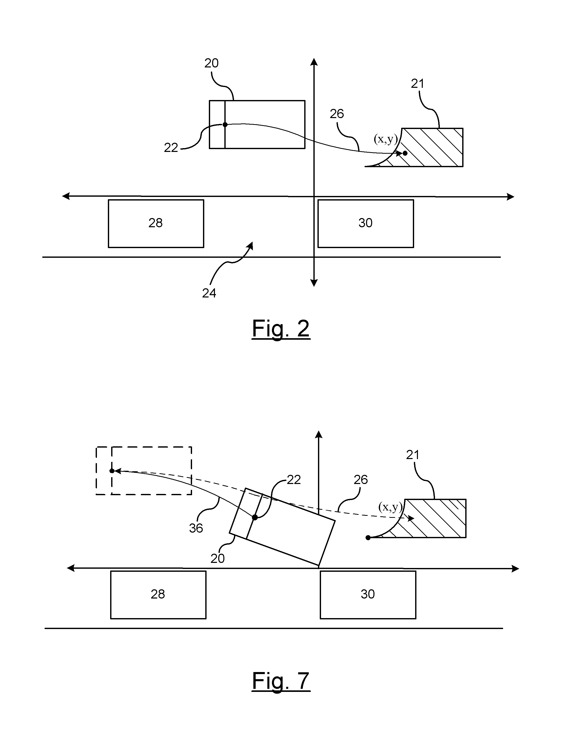
[0003]An advantage of an embodiment is the maneuvering of a vehicle to a feasible region of starting locations for initiating a parallel parking maneuver. The feasible region identifies a region for where a vehicle can initiate a successful parking maneuver; however, the vehicle must be located within the feasible region to initiate the parallel parking maneuver. As a result, the embodiments herein describe the maneuvering of the vehicle from a current position to a region of feasible starting locations. This avoids the driver receiving a message that the parking maneuver is not feasible and looking for a next available parking space. That is, rather than just actuating a message identifying that the vehicle cannot be parked, the system autonomously or semi-autonomously guides the vehicle from a current position to the region of feasible starting locations. If obstacles are encountered, then the system attempts to reconfigure the target path for maneuvering the vehicle to the region of feasible starting locations.

Problems solved by technology

Parallel parking a vehicle between two vehicles is often a difficult task for a driver.
As a result, based on the location and / or orientation of the vehicle, the determined intended trajectory path may not be suitable for parallel parking the vehicle based on the vehicle's current location / orientation.

Method used


Image

  • Directing vehicle into feasible region for autonomous and semi-autonomous parking
  • Directing vehicle into feasible region for autonomous and semi-autonomous parking
  • Directing vehicle into feasible region for autonomous and semi-autonomous parking

Examples


Embodiment Construction

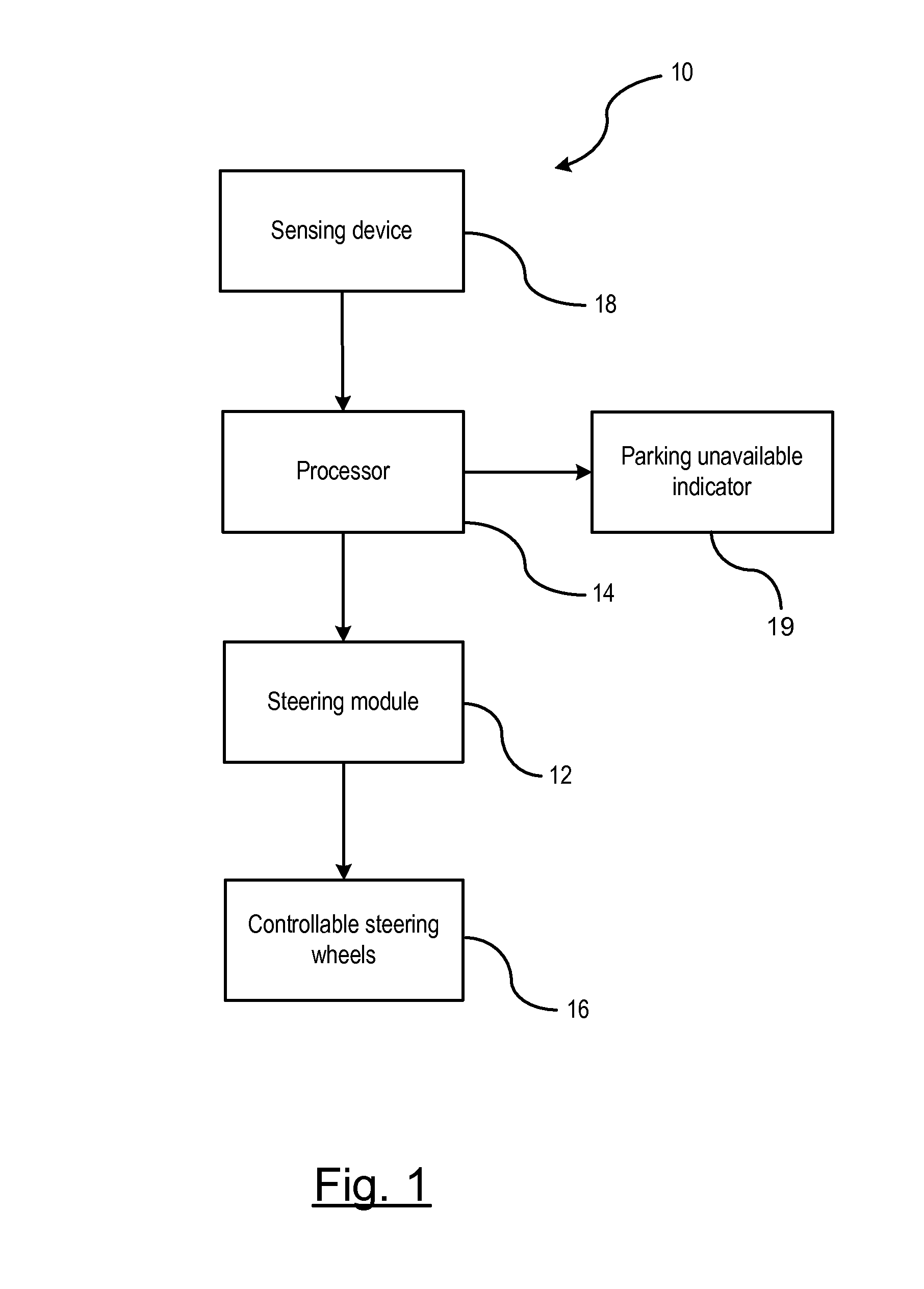
[0014]There is shown in FIG. 1 an embodiment of an autonomous steering system 10 for parallel parking a vehicle 20. The autonomous steering system 10 includes a steering module 12 and a processor 14 for controlling steerable wheels 16 of the vehicle. The steering module 12 may be an electronic module or similar device that is capable of turning the steerable wheels 16 without a driver's steering demand via a steering wheel of the vehicle. The processor 14 provides control input signals to the steering module 12, such as a conventional electronic power steering module, for controlling the turning of the steerable wheels during a parking maneuver. The processor 14 may be separate from the steering module 12 or may be integrated within the steering module 12 as a single unit. It should be understood that the system and techniques described herein also apply to semi-autonomous steering systems.

[0015]The autonomous steering system 10 further includes a sensing device 18 for detecting obj...


PUM


Abstract

A method of guiding a vehicle to a region for initiating a parallel parking maneuver. A region of feasible starting locations for successfully performing a parallel parking maneuver is determined by a processor. A position of the vehicle relative to the region of feasible starting locations is determined. A determination is made whether the vehicle is in a zero heading position. The vehicle is guided along an initial target path by controlling a steering actuator until the vehicle is in a zero heading position relative to the road of travel in response to the vehicle is not in the zero heading position. A planned path is generated that includes two arc-shaped trajectories extending between the vehicle at the zero heading position and a position within the region of feasible starting locations as determined by the processor. The steering actuator is controlled to follow the planned path to the feasible region.

Description

BACKGROUND OF INVENTION[0001]An embodiment relates generally to parallel parking of a vehicle.[0002]Parallel parking a vehicle between two vehicles is often a difficult task for a driver. Semi-autonomous parking systems aid the driver in performing difficult parking maneuvers such as parallel parking. Such systems either guide the driver in steering the vehicle through its intended trajectory path or increase / decrease power steering efforts when the driver of the vehicle has deviated from the intended trajectory path. In such systems, an intended trajectory path is determined based on the available space between a pair of objects. However, such paths are often determined for a predetermined point where the vehicle must be located to initiate the parking maneuver. That is, the intended trajectory path may be determined for a position other than where the vehicle is actually located. As a result, based on the location and / or orientation of the vehicle, the determined intended trajecto...

Claims


Application Information

Patent Timeline
Patent Type & Authority Patents(United States)
IPC IPC(8): B62C3/00B60G17/018B62D5/04
CPCB62D5/0463B62D6/00B62D15/0285
Inventor MOSHCHUK, NIKOLAI K.LITKOUHI, BAKHTIAR BRIANCHEN, SHIH-KEN
Owner GM GLOBAL TECH OPERATIONS LLC
Learn More