
Load carriage connector and system

a load carriage and connector technology, applied in the direction of arms wearables, fishing, scarves, etc., can solve the problems of not being easily customizable, affecting the reliability of connection, so as to facilitate connection reliability and speed, facilitate the decoupling of the connector halves, and facilitate the mounting and demounting of user-carried loads.

Active Publication Date: 2014-10-14
THE UNITED STATES OF AMERICA AS REPRESETNED BY THE SEC OF THE AIR FORCE
View PDF33 Cites 21 Cited by
  • Summary
  • Abstract
  • Description
  • Claims
  • Application Information

AI Technical Summary

Benefits of technology

Facilitates rapid and secure mounting and demounting of loads, reducing user fatigue and improving survivability by efficiently distributing weight and allowing for quick configuration changes, while eliminating the need for multiple load-bearing belts.

Problems solved by technology

Additionally, without auxiliary mounting points, the frameless backpack is subject to significant bouncing or swaying as the user runs or jumps.
While these frame-based systems improve the user's load carrying capability, they are not readily customizable.
Additionally, the fasteners used with the auxiliary belt attachment point often makes attachment and removal much more time consuming when compared with simple frameless designs.
While the MOLLE system does allow for increased user customization, the system does not empower the user to rapidly configure the gear as changes in the activity or mission arise.
Additionally, the MOLLE system does not improve upon the speed in which the entire load carriage system is donned and doffed.
For example, during a vehicular crash, rollover, or explosion, a user may be trapped by the bulk and weight of his pack.
Additionally, a soldier accidentally thrown into a waterway may be unable to remain buoyant when faced with the additional weight on his back.
As one of ordinary skill in the art will recognize, time consuming and complicated mounting systems may significantly reduce user survivability in the above mentioned situations.

Method used


Image

  • Load carriage connector and system
  • Load carriage connector and system
  • Load carriage connector and system

Examples


Embodiment Construction

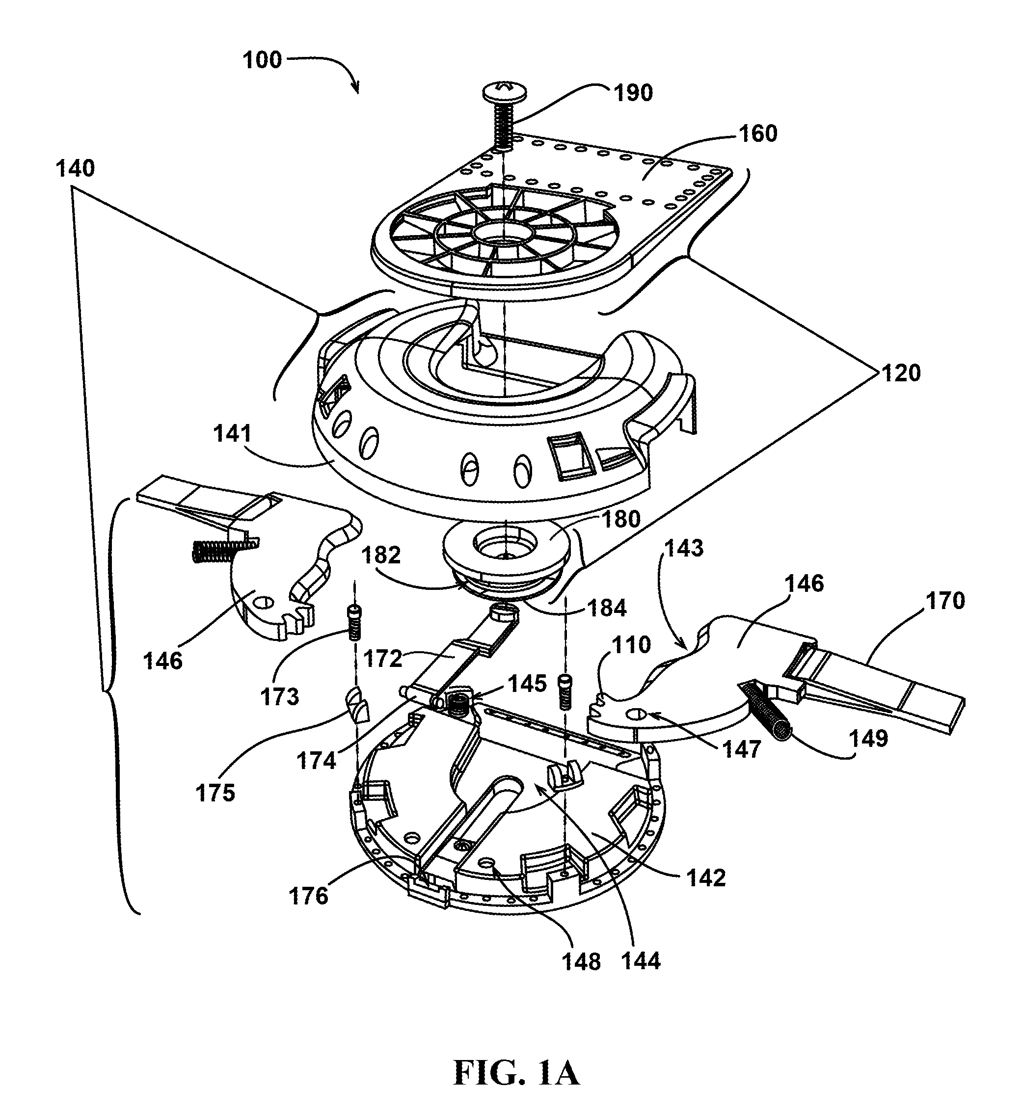
[0023]The present invention provides a load carriage connector and connector system for rapidly attaching and detaching loads. The load carriage connector comprises a male and a female connector half that may be mounted to a load distributor such as a load-bearing belt. As part of a connector system, a ruck pin assembly may be attached to a load such as a rucksack, and the ruck pin assembly engages the load carriage connector. The system may further comprise a tactical vest to which the load is further coupled. The load may be quickly detached and reattached without the need to remove the load-bearing belt and / or the load carriage connector. In addition, the load carriage connector may comprise connectors that allow the two halves to electronically interface.

[0024]Civilians and military alike who wear heavy rucksacks (deployed soldiers, campers, rangers, firefighters, hikers, etc.) may benefit from the presently disclosed invention. The presently disclosed load carriage connector an...


PUM


Abstract

A load carriage connector and system for rapid mounting and demounting of a user-carried load. The connector utilizes two mating halves comprising a male connector half and a female connector half. The connector is configured to allow mating under various angles of approach, allowing the user to reliably couple the system even under conditions in which the user is unable to view the orientation of the connectors. Additionally, the configuration of the connector system allows the user to quickly and efficiently decouple the connector halves, even while under tensile or shear load.

Description

CROSS-REFERENCE TO RELATED APPLICATIONS[0001]This application claims the benefit of U.S. Provisional Application No. 61 / 608,507, filed on Mar. 8, 2012, entitled “Scalable Load Carriage Connector System,” which is herein incorporated by reference in its entirety.RIGHTS OF THE GOVERNMENT[0002]The invention described herein may be manufactured and used by or for the Government of the United States for all governmental purposes without the payment of any royalty.BACKGROUND OF THE INVENTION[0003]1. Field of the Invention[0004]The invention generally relates to the field of personal load bearing equipment. More specifically, the invention relates to rapidly detachable load carriage connectors and systems.[0005]2. Description of the Related Art[0006]Soldiers, especially members of agile and rapidly deployable units, civilians engaged in activities such as hiking, and public safety personnel such as persons engaged search and rescue missions all require reliable systems for the effective ca...

Claims


Application Information

Patent Timeline
Patent Type & Authority Patents(United States)
IPC IPC(8): A45F5/02A45F3/04A44B11/00A45F3/02A45F3/06A45F3/14
CPCA44B11/005A45F3/14A45F2005/026A45F2003/025A41D2400/48A45F3/06Y10T24/13Y10T24/45482
Inventor BURNETT, GREGORY M.SEDILLO, MICHAEL R.
Owner THE UNITED STATES OF AMERICA AS REPRESETNED BY THE SEC OF THE AIR FORCE
Learn More