
Object identification from image data captured from a mobile aerial platforms

a technology of image data and aerial platforms, applied in the field of image data processing, can solve the problems of high human error, time-consuming and expensive, and the inability to apply techniques to image data comparing temporal sequences of images obtained from different viewpoints,

Active Publication Date: 2014-09-09
BAE SYSTEMS PLC
View PDF9 Cites 10 Cited by
  • Summary
  • Abstract
  • Description
  • Claims
  • Application Information

AI Technical Summary

Benefits of technology

The present invention provides an image processing method, apparatus, and computer program for detecting changes in image content between different but repeatable viewpoints. The method involves capturing image data from a sequence of images of a scene from different viewpoints and associating the images with their respective viewpoint identification. The images are then tracked to detect any changes in a region of interest between the captured images and a reference image for the same viewpoints. The changes can be detected by comparing the calculated points in an eigenspace projection created from the images with previously obtained points. The invention has applications in various fields such as surveillance, sports arenas, and security.

Problems solved by technology

This can be tedious and hence lead to potentially high levels of human error, as well as being time-consuming and expensive.
However, although conventional automatic image processing techniques are available for use with sequences of images obtained from static viewpoints, such techniques cannot readily be applied to image data comparing a temporal sequence of images of a scene obtained from differing viewpoints (for example image data from a mobile platform, for example an unmanned aerial vehicle (UAV), or for example image data from a statically positioned camera that sweeps over a changing field of view), due to the image transformations that arise from the images in the sequence being from differing viewpoints.

Method used


Image

  • Object identification from image data captured from a mobile aerial platforms
  • Object identification from image data captured from a mobile aerial platforms
  • Object identification from image data captured from a mobile aerial platforms

Examples


Embodiment Construction

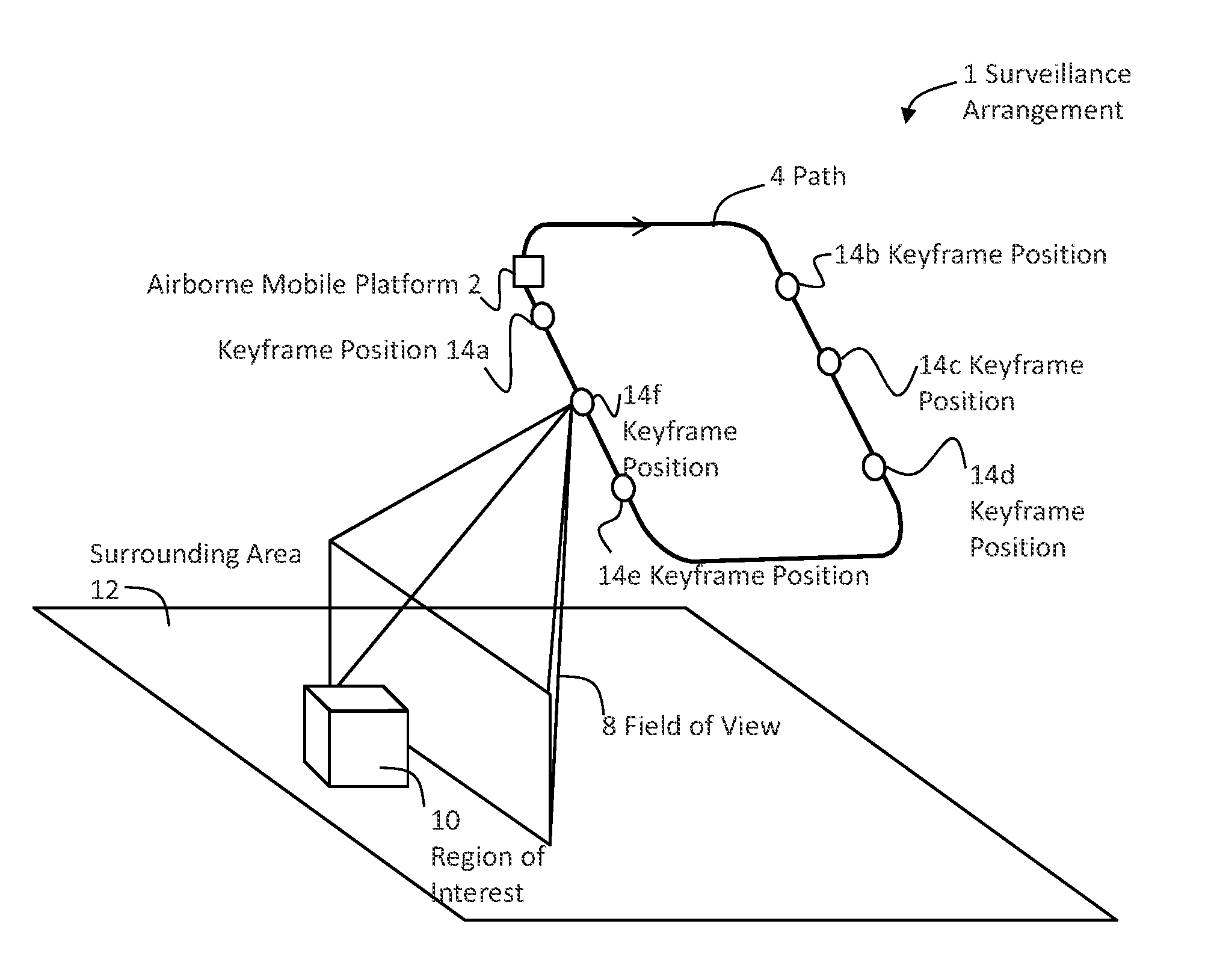
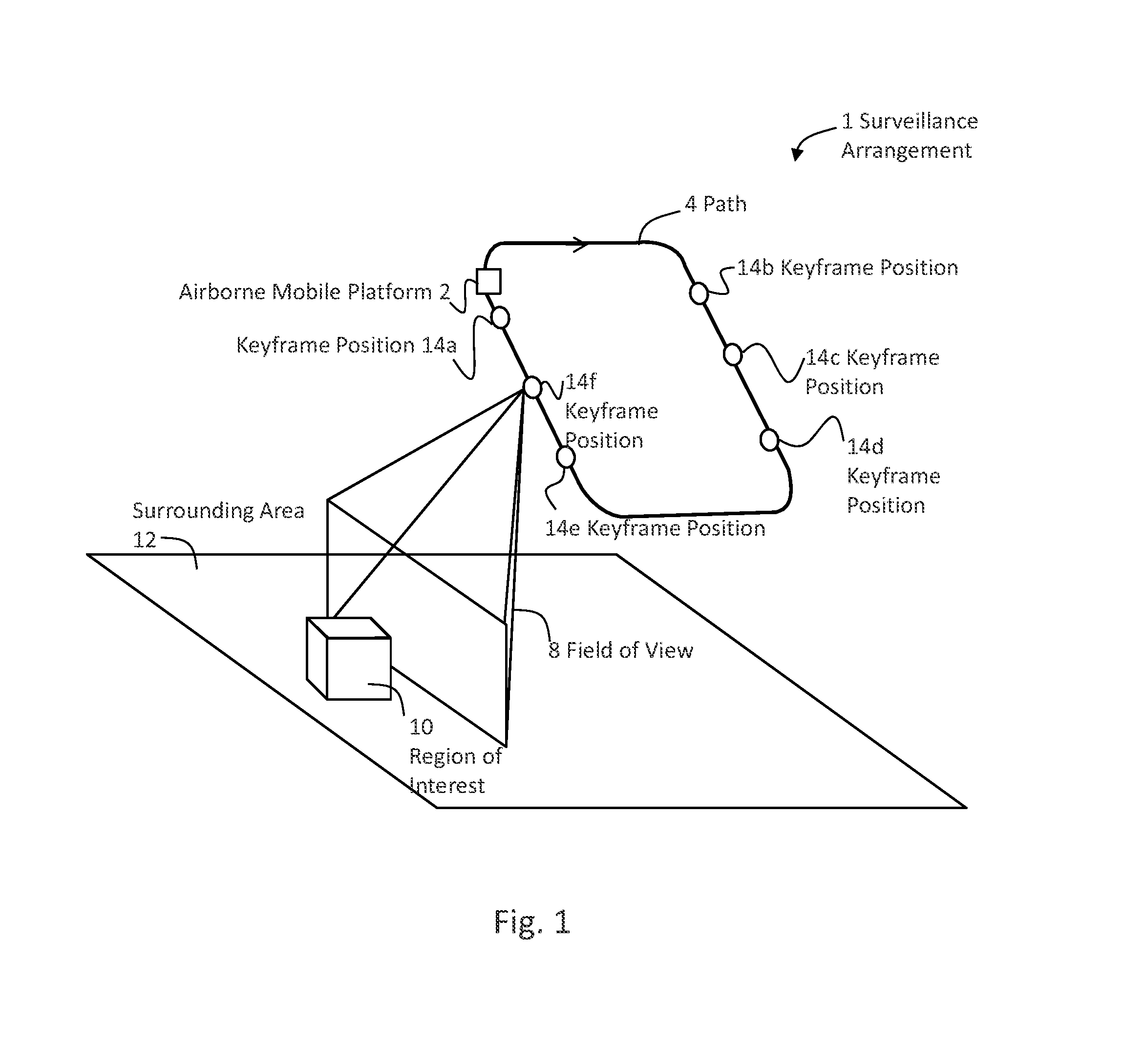
[0030]FIG. 1 is a schematic illustration (not to scale) of a surveillance arrangement in which an embodiment of the invention may be implemented.

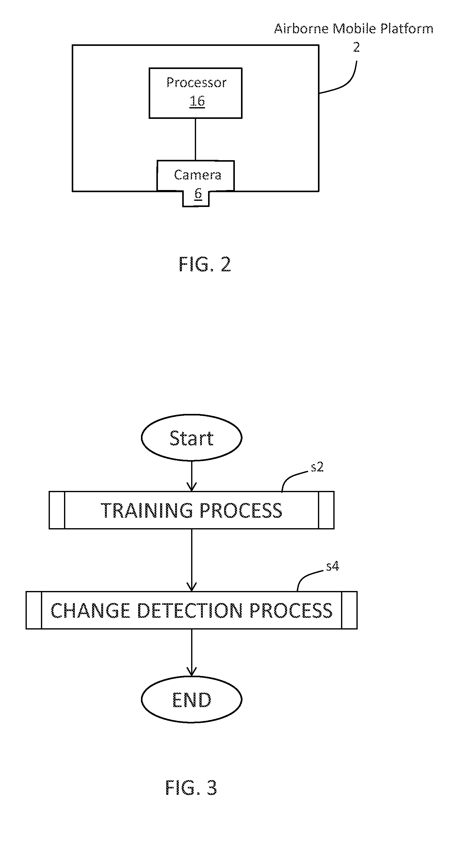
[0031]In the surveillance arrangement 1, an airborne mobile platform 2 travels repeatedly around a closed-loop surveillance path 4. The mobile platform 2 comprises a camera 6 (as shown schematically in FIG. 2) that captures image data as the mobile platform travels around the surveillance path 4. In this example the mobile platform is carried on the surveillance path 4 by an unmanned aerial vehicle (UAV) (not shown in FIG. 1). At each position the camera has a respective field of view 8 (one such field of view 8 for one such position on the surveillance path 4 is shown by way of example in FIG. 1). In this example a region of interest (ROI) 10 within a surrounding area 12 is determined and monitored, as will be described in more detail later below. The ROI 10 may, for example, be a specific building and an area of land immediately surroundi...


PUM


Abstract

An image processing method includes: capturing image data from a sequence of images of a scene from different but repeatable viewpoints; associating captured images with a respective viewpoint identification; tracking a region of interest in the sequence of images; performing an eigenspace projection for the respective images to calculate respective points in the eigenspace projection; and comparing the calculated points to points previously obtained for a reference image for substantially the same viewpoints. A change between a calculated point and a corresponding previously obtained point indicates a change in the image content of the region of interest between the corresponding captured image and the corresponding reference image for a substantially same viewpoint.

Description

FIELD OF THE INVENTION[0001]The present invention relates to processing of image data that comprises images of a scene obtained from differing viewpoints, for example image data from a mobile platform, for example an unmanned aerial vehicle (UAV), or for example image data from a statically positioned camera that sweeps over a changing field of view.BACKGROUND[0002]Processing of dynamic image scenes is often carried out by a human operator visually monitoring a transmitted video feed. This can be tedious and hence lead to potentially high levels of human error, as well as being time-consuming and expensive.[0003]Hence automatic image processing is desirable, to either fully detect events or items of interest, or to provide intermediate data (meta-data) alerting a human operator and / or further automatic processing to a possible detection of an event or item of interest.[0004]However, although conventional automatic image processing techniques are available for use with sequences of i...

Claims


Application Information

Patent Timeline
Patent Type & Authority Patents(United States)
IPC IPC(8): G06K9/00G06V20/13G06T7/20
CPCG06K9/3233G06T7/206G06K9/0063G06T2207/30232G06T2207/20081G06T2207/20048G06T7/262G06V20/13
Inventor THUEUX, YOANN PAUL GEORGESCARTER, NICHOLAS LAURENCE
Owner BAE SYSTEMS PLC
Learn More