
Urination control device

a control device and urination technology, applied in the direction of valve operating means/release devices, prosthesis, catheters, etc., can solve the problems of male-specific urinary incontinence, unpleasant sensation and objectionable odor, and achieve the effect of preventing urinary incontinence, accuracy and controllability, and reliably closing and opening

Active Publication Date: 2014-08-12
CHEIRON JAPAN CO
View PDF33 Cites 9 Cited by
  • Summary
  • Abstract
  • Description
  • Claims
  • Application Information

AI Technical Summary

Benefits of technology

[0039]According to the urination control device of the present invention, a patient can autonomously urinate in a state close to spontaneous urination without resorting manipulation conducted externally and using an instrument by adjusting fluid pressure exerted on the urination control device, i.e. the intravesical pressure with the abdominal pressure to control the urination. Hence, safety, accuracy and the controllability for reliably closing and opening can be ensured to prevent the urinary incontinence. The intravesical pressure in opening and closing a control valve can be variously designed to cope with the condition of the patient.
[0040]Further, the urination control device can be applied to both men and women and ensure the safety, accuracy and the controllability for reliably closing and opening since the device is simple in structure without using a spring or the like. With the simple structure, adulterants such as depositions to be evacuated into the urine are difficult to accumulate and contaminate, thereby to prevent infection and contamination by employing safe constituent materials and elements. Thus, this device is desirable for being embedded in the body while maintaining the QOL of the patients.
[0041]Furthermore, the device is simple in configuration and structure, saving on space and can be disposed near the urinary bladder through the urethra. That is, the device can easily be fitted in the meatus urethra, i.e. the bladder sphincter and detached therefrom without getting adverse effects, thereby to improve QOL of the patients.
[0042]The device of the invention makes it possible to control urination by voluntarily applying the abdominal pressure by a patient who has aftereffects from injury of the bladder sphincter or dominant nerve neurectomy, which are possibly caused frequently in an operation of radical prostatectomy for carcinoma prostata, or urinary incontinence or urethral hypermobility due to paralytic symptoms of the bladder sphincter, but is not serious enough to turn to an operative procedure or inoperable or undesirous of an operation for any reason. Furthermore, the device of the invention requires does not need a napkin or other supplies for urine absorption in preparation for urination, thus being unbothered by unpleasant sensation of usage and fetid odor. Due to these effects, the QOL of the patients can be improved.

Problems solved by technology

The stress urinary incontinence tends to involuntarily occur when experiencing abdominal pressure due to coughing, sneezing, lifting weights, walking for long time, singing, laughing or yelling, consequently resulting in causing suffering.
Furthermore, the male-specific urinary incontinence may be developed due to disturbance of the bladder sphincter which occurs frequently in patients undergoing a total relaxation to treat prostate cancer or aftereffects suffered from indispensable dominant nerve section, aftereffects of radiation by radiotherapy for prostate cancer or prostate enlargement related surgery, or inadvertent nerve cutting happened during a surgery operation.
However, these supplies must be replaced at frequent intervals and abhorrently cause unpleasant sensation and an objectionable odor in the event of attachment or replacement.

Method used


Image

  • Urination control device
  • Urination control device
  • Urination control device

Examples


first embodiment

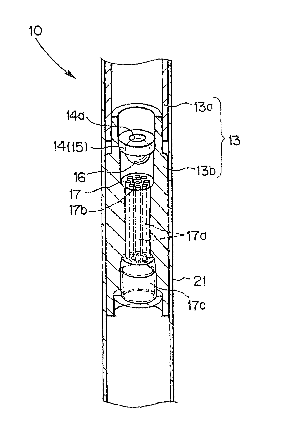
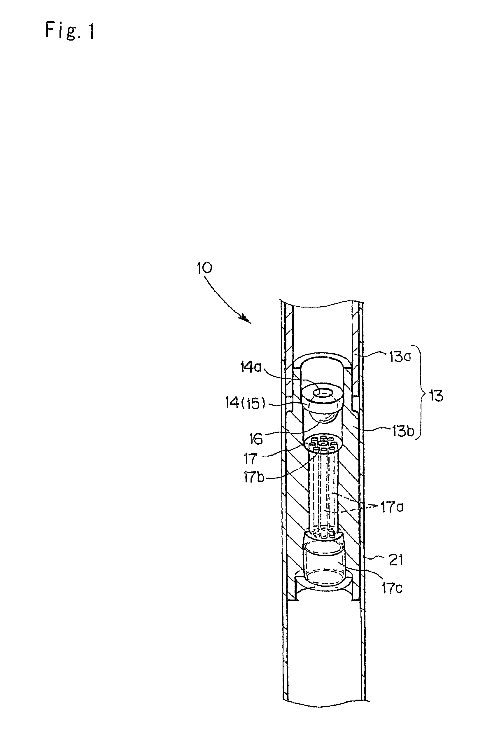
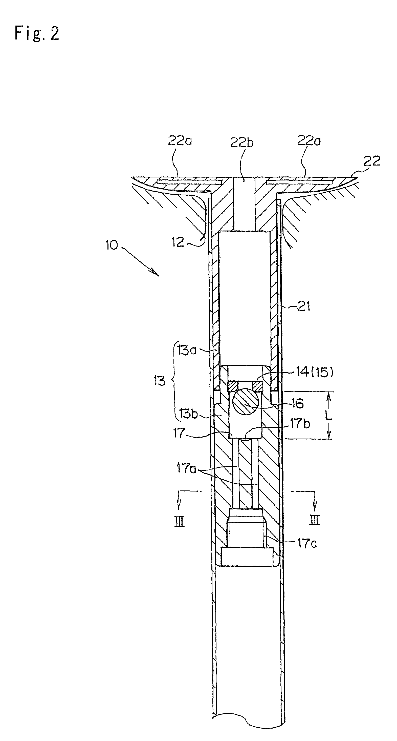
[0056]FIG. 1 is a partially broken perspective view showing the principal part of the urination control device according to a first embodiment of the present invention, FIG. 2 is a sectional side view of the urination control device of FIG. 1, FIG. 3(a) is a cross sectional view taken along line III-III in FIG. 2, FIG. 3(b) is a plan view of a restrainer in the device of FIG. 2, and FIG. 3(c) is a front view showing a removing tool used in the first embodiment.

[0057]As shown in FIGS. 1 and 2, the urination control device 10 generally comprises a conduit 13 to be inserted into the urethra 12, an upstream restraint member 14 located upstream of the conduit 13, a control spheric body 16 serving as the control member of the present invention, which is located downstream of the upstream restraint member 14 in the conduit 13, and a downstream restraint member 17 located downstream of the control member in the conduit 13.

[0058]The conduit 13 is inserted into the urethra 12 and what is call...

second embodiment

[0083]FIG. 6(a) is a sectional view of the principal part of the urination control device according to the second embodiment of the invention, and FIG. 6(b) is a sectional view taken along line VI-VI in FIG. 6(a). The elements indicated by like reference symbols with respect to those of the first embodiment have analogous structures and functions to the urination control device 10 of the first embodiment and will not be described in detail again.

[0084]In the urination control device 60 in this embodiment comprises a conduit 63 formed of one part of a flexible plastic tube, in which an upstream restraint member 64 and downstream restraint member 67 are assembled by welding or concaves / convexs couple means.

[0085]The upstream restraint member 64 is made of flexible plastic as with the conduit 63 and formed in a annular shape having a round through hole 64a in its substantial center. A magnet 65 is embedded in the flexible plastic body. The circumferential periphery of the opening of th...

third embodiment

[0090]FIG. 7 is a sectional side view of the principal part of the urination control device according to the third embodiment of the present invention; FIG. 8 is a partially broken perspective view of the principal part of the urination control device of FIG. 7; FIG. 9 is a cross sectional view taken along line IX-IX in FIG. 7; FIG. 10 is a sectional view of the principal part, showing the effect of the urination control device of FIG. 7; FIG. 11(a) is a plan view showing the restrainer in the spread state of the urination control device of FIG. 7, and FIG. 11(b) is a cross sectional view taken along line XI-XI in FIG. 11(a), FIG. 12 is a sectional view of the principal part, showing the setting aspect of the urination control device of FIG. 7; andFIG. 13 is a plan view showing the restraint member in the spread state of the urination control device of FIG. 12.

[0091]As shown in FIG. 7 and FIG. 8, the urination control device 80 has a conduit 83 being inserted into the urethra, and a...


PUM


Abstract

A urination control device includes a conduit to be inserted into the urethra, an upstream restraint member located upstream of the conduit and having a through hole, a control member located on the downstream side from the upstream restraint member in the conduit, and a downstream restraint member located on the downstream side from the control member in the conduit, wherein the upper restraint member and control member attract each other with magnetic force, and the control member is brought in contact with the opening portion of the through hole in the upstream restraint member at least in the state exerting no fluid pressure on the upstream side so as to block passage of fluid through the upstream restraint member and admit the passage of fluid through the downstream restraint member in the state engaged with the control member.

Description

TECHNICAL FIELD[0001]The present invention relates to a urination control device for preventing urinary incontinence.BACKGROUND ART[0002]The urinary incontinence is involuntary leakage of urine which can be proved objectively and defined as urinary leakage closely related to human life from social and hygiene perspectives (according to the International Incontinence Society). Now, the urinary incontinence is increasing specifically in men and women over 40 years old. Among types of urinary incontinence, stress urinary incontinence occurs most frequently and, supposedly, accounts for half or more of urinary incontinence in women. The stress urinary incontinence tends to involuntarily occur when experiencing abdominal pressure due to coughing, sneezing, lifting weights, walking for long time, singing, laughing or yelling, consequently resulting in causing suffering. Especially in women, the number of postmenopausal patients has markedly increased and it seems that the stress urinary i...

Claims


Application Information

Patent Timeline
Patent Type & Authority Patents(United States)
IPC IPC(8): A61M27/00
CPCA61M25/04A61M25/0017A61M2205/0266A61M2210/1085A61M2210/1089A61F5/453A61M39/22
Inventor YUGARI, MASAZUMITAKAGI, HIDENORI
Owner CHEIRON JAPAN CO
Learn More