Network-to-network bridge

a network bridge and network technology, applied in the field of computer network, can solve the problems of limiting data transmission rate, data transmission rate also limited, and becoming bottleneck of data transmission ra

Active Publication Date: 2014-08-05
VIA TECH INC
View PDF9 Cites 0 Cited by
  • Summary
  • Abstract
  • Description
  • Claims
  • Application Information

AI Technical Summary

Problems solved by technology

Because the computer system, the server, and the network switch respectively need a network adapter for transmitting / receiving network packets to / from a network connection, the performance of a network access layer of the network adapter is thus becoming the bottleneck limiting the data transmission rate.
In addition, the data transmission rate is also limited to the lowest data transmission / receiving rate because two transmission terminals will follow the same transmission rate to exchange network packets.
Obviously, the network transmission rate will be limited by the network adapter which owns the lowest transmission rate among network adapters in the network connection.
Practically, the total transmission rate will be lower than the aforementioned because there is additional time-cost for packet error detections.
However, such a structure is becoming inefficiency for cloud computing or wireless communication base stations / server rooms because those servers therein are requested to provide more and more services.
As aforementioned, the transmission rate and error detection operations of the network access layer affect the system efficiency, and a lot of packet encapsulation and decapsulation operations performed within the neighboring main system and subsystems significantly cause delays to the transmission rate of the entire system.

Method used


Image

  • Network-to-network bridge
  • Network-to-network bridge
  • Network-to-network bridge

Examples


Embodiment Construction

[0025]The following description is of the best-contemplated mode of carrying out the invention. This description is made for the purpose of illustrating the general principles of the invention and should not be taken in a limiting sense. The scope of the invention is best determined by reference to the appended claims.

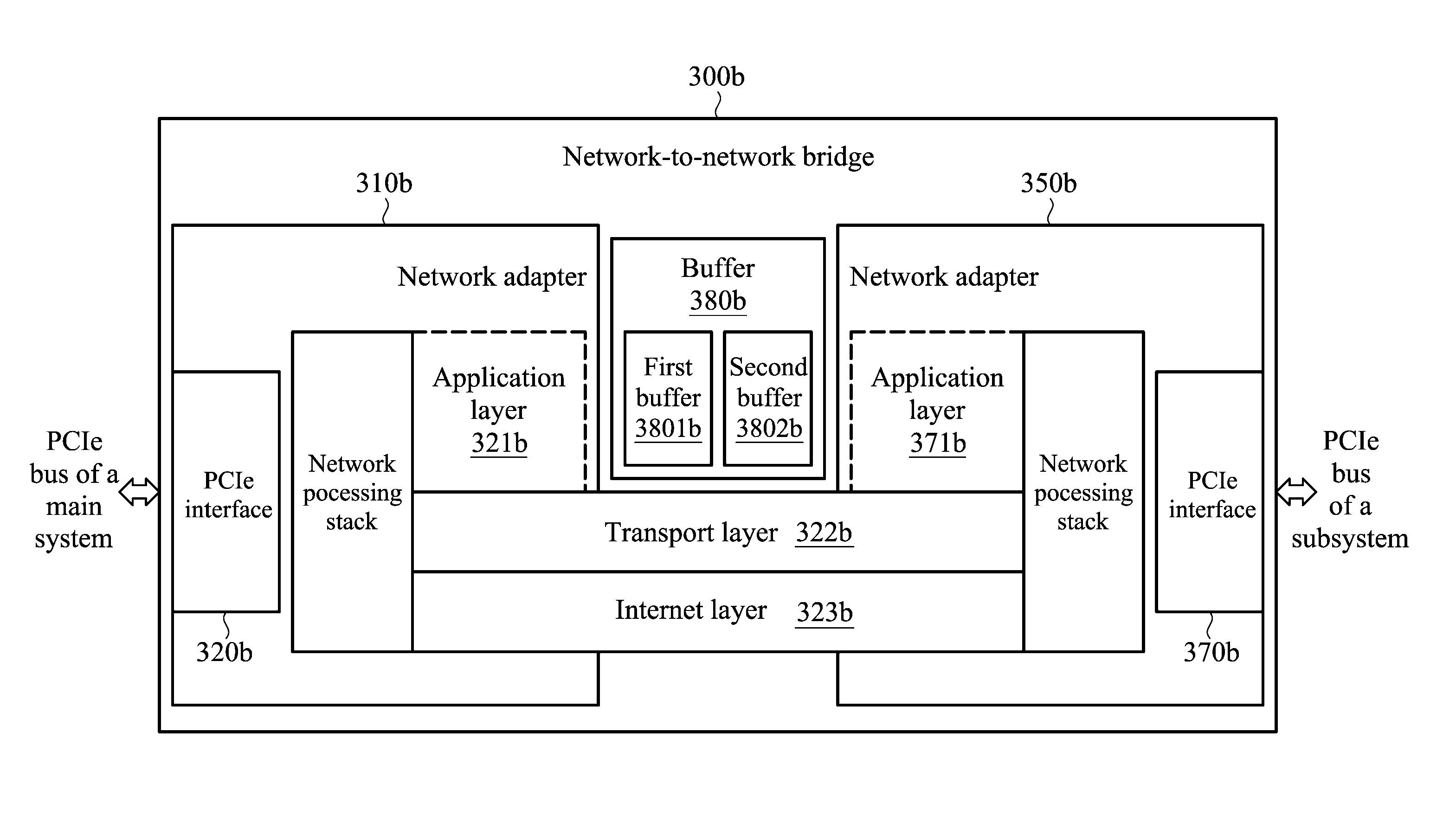
[0026]To solve the problem of a low network transmission rate raised by the network access layer, a network system is provided by inserting a subsystem into a slot of a main system. The main system and the subsystem share a transport layer and an Internet layer but a network access layer is removed therebetween. A Peripheral Component Interconnect express (PCIe) bus with a high transmission rate is used to transfer data between the subsystem and the main system, such that a network access layer which is necessary in the conventional is therefore unnecessary for the main system and the subsystem of the invention, and the data transmission rate between the main system an...


PUM


Abstract

A network-to-network bridge is provided. In one embodiment, the network-to-network bridge is coupled between a main system and a subsystem system. The main system includes a slot to couple with the subsystem, wherein the slot complies with the PCIe standard. The network-to-network bridge includes a transport layer and an internet layer but lacks of a network access layer allocated between the first main system and subsystem so as to transfer data by following the PCIe standard therebetween. The network-to-network bridge transfers data between the main system and the subsystem by accessing and employing their MAC addresses, and the network-to-network bridge can be allocated in the mainboard of the main system or the subsystem.

Description

CROSS REFERENCE TO RELATED APPLICATIONS[0001]This application claims the benefits of U.S. Provisional Application No. 61 / 501,713, filed on Jun. 27, 2011 and TW patent application No. 101120856, filed on Jun. 11, 2012, the entireties of which are incorporated by reference herein.BACKGROUND OF THE INVENTION[0002]1. Field of the Invention[0003]The invention relates to computer network, and more particularly to a computer network with a transmission layer and an Internet layer but without a network access layer shared between computer systems.[0004]2. Description of the Related Art[0005]Ordinarily, a computer system is connected to a server via an Ethernet. Basically, the connection between the computer and the server may be a one-to-one connection or one-to-multiple connection. Referring to FIG. 1A, a schematic diagram of a computer system 120 and a server 110 with a one-to-one connection is shown. Referring to FIG. 1B, a schematic diagram of a plurality of computer systems 182, 184, a...

Claims


Application Information

Patent Timeline
Patent Type & Authority Patents(United States)
IPC IPC(8): G06F15/16
CPCH04L49/00G06F13/385
Inventor CHEN, SHIH-JUI
Owner VIA TECH INC
Why Eureka
Try Eureka