
Sleep monitoring system

a monitoring system and sleep technology, applied in the field of sleep monitoring system, can solve the problems of inability to accurately record extremely low voltage eeg signals, complex monitoring equipment of polysomnogram, and inability to monitor sleep patterns, etc., and achieve the effect of improving the performance of already-selected features

Active Publication Date: 2014-07-22
RESMED SENSOR TECH
View PDF9 Cites 1 Cited by
  • Summary
  • Abstract
  • Description
  • Claims
  • Application Information

AI Technical Summary

Benefits of technology

[0035]In one embodiment, said process executes passes which add a feature that most improves performance to already-selected features.

Problems solved by technology

First of all, polysomnogram monitoring equipment is complex and generally needs to be operated and analysed in a clinic by skilled technicians.
This is a costly and time-consuming process.
If the polysomnogram system is operated by a patient at home, there is the requirement that the electrodes are attached correctly, and in particular that the EEG electrodes are correctly placed and attach, or otherwise the extremely low voltage EEG signals will not be recorded correctly.
Furthermore, the use of a number of electrodes attached to the head during sleep is uncomfortable and disrupts the patient's sleep.
However, such systems have the disadvantage that they can only distinguish between sleep and wake, with poor accuracy in patients with sleep disorders.
The prior art systems do not appear to analyse specific sleep stages sufficiently to recognise periods of wakefulness.
In addition, where stages such as REM and non-REM are differentiated it appears that the performance is quite poor as the decision is based on comparison of a single parameter with a previously determined threshold value.
Therefore the current state of the art in determining sleep stages is limited by (a) the need to directly measure brain activity, and (b) poor performance when using observations of single parameters of cardiac activity.

Method used


Image

  • Sleep monitoring system
  • Sleep monitoring system
  • Sleep monitoring system

Examples


examples

Feature Extraction

[0062]In an automated sleep staging system features are extracted from each 30 s. Sample data was collected from a database composed of overnight recordings from 37 subjects.

RR-Interval Series Features:

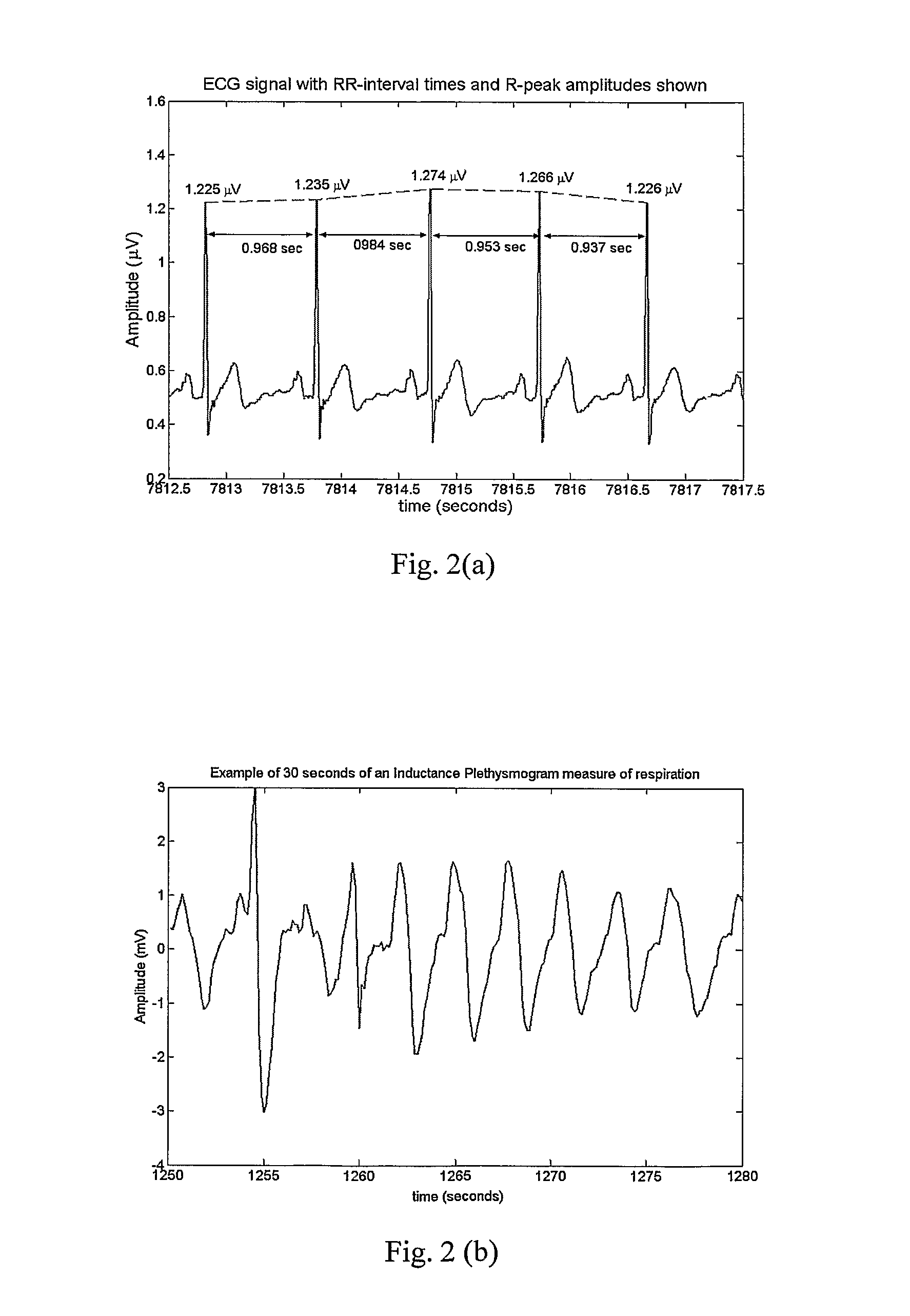
[0063]To calculate a power spectral density estimate, the data (RRnorm intervals falling within the epoch) from the epoch is zero-meaned, windowed (using a Hanning window), and the square of its Discrete Fourier Transform (DFT) is taken as a single periodogram estimate of the interval based power spectral density. The x-ordinate of this estimate is in cycles / interval, which can be converted to cycles / second by dividing by the mean RR for the epoch. From this spectral estimate, five features are calculated:[0064]the logarithm of the normalized LF (power in the 0.05-0.15 Hz band),[0065]the logarithm of the normalized HF (power in the 0.15-0.5 Hz band), where normalization is achieved by dividing by the total power in the VLF, LF, and HF bands (0.01-0.5 Hz),[0066]the LF...


PUM


Abstract

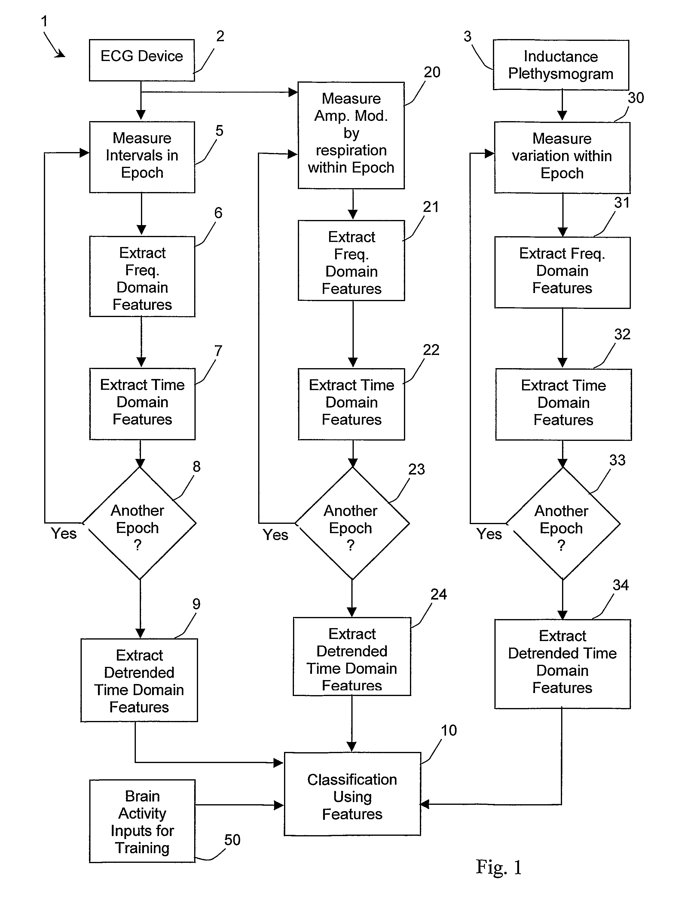
A sleep monitoring system includes an ECG device (2) and a respiration inductance plethysmogram (3) which monitor cardiac activity and physical (ribcage) respiration respectively and feed representative signals to a digital data processor. Operations (5-9) process the beat interval data, while in a second thread, operations (20-24) independently process the amplitude modulation of the ECG data caused by the respiratory motion of the subject. The inductance plethysmogram device (3) provides an input to the processor which represents respiration as directly monitored independently of the ECG. Operations (30-34) process this direct respiration data independently and in parallel, in a third thread. All extracted features are fed to a classifier which in step (10) combines selected combinations of features to make decisions in real time.

Description

CROSS-REFERENCE TO RELATED APPLICATIONS[0001]This application is a National Stage entry under 35 U.S.C. §371 of International Application PCT / IE2005 / 000122, filed on Nov. 2, 2005. International Application PCI / IE2005 / 000122 claims priority to Irish application 2004 / 0731 filed on Nov. 2, 2004. The entire contents of each of these applications are incorporated herein by reference.BACKGROUND[0002]1. Field of the Invention[0003]The invention relates to monitoring of a person's sleep pattern.[0004]2. Prior Art Discussion[0005]It is known to provide a system to receive and process signals from sensors in order to monitor a person's sleep pattern. In one approach sleep stages are determined using signals from a polysomnogram system, in which the sleep staging component is based on measuring electroencephalograms (EEG) which are a direct measurement of brain activity. This approach has a number of disadvantages. First of all, polysomnogram monitoring equipment is complex and generally needs...

Claims


Application Information

Patent Timeline
Patent Type & Authority Patents(United States)
IPC IPC(8): G06F19/00A61B5/02
CPCA61B5/113G06F19/345A61B5/7264A61B5/4812A61B5/02405A61B5/4806A61B5/7267G16H50/20A61B5/7278
Inventor HENEGHAN, CONORREDMOND, STEPHEN
Owner RESMED SENSOR TECH
Learn More