
Adjustable weight asssembly for weight training machine

a weight training machine and adjustable technology, applied in the field of adjustable weight assembly, can solve the problems of time-consuming and labor-intensive, and the conventional weight training machine does not have a satisfied adjustable weight device for the user

Inactive Publication Date: 2014-07-15
LO CHIU HSIANG
View PDF8 Cites 30 Cited by
  • Summary
  • Abstract
  • Description
  • Claims
  • Application Information

AI Technical Summary

Benefits of technology

The present invention is a weight training machine with an adjustable weight assembly. It consists of a rail, a movable member, and multiple weights. The movable member is connected to a rod and receives a force applied by a force applying unit so as to move along the rail. Each weight has a latitude hole and a longitudinal hole with a pin extending therethrough. The adjustable device includes a driving unit, a movable part, and multiple pivotal members. When the movable part moves along the rail, the pivotal member is pivoted to decide the engagement between the pin and the through hole so that the user can adjust the number of the weights. The invention also provides two weight devices and two adjustment devices with a connection member connected between the two respective movable members. The patent describes a further technical effect of the invention to adjust the total load when using the weights training machine.

Problems solved by technology

However, the prior arts do not have linked pins to automatically choose the number of the weights so that the user has to insert the pins one by one when positioning the weights, and this requires time.
Besides, the conventional weight training machines do not have satisfied adjustable weight device for the user to adjust the weight as desired.

Method used


Image

  • Adjustable weight asssembly for weight training machine
  • Adjustable weight asssembly for weight training machine
  • Adjustable weight asssembly for weight training machine

Examples


Embodiment Construction

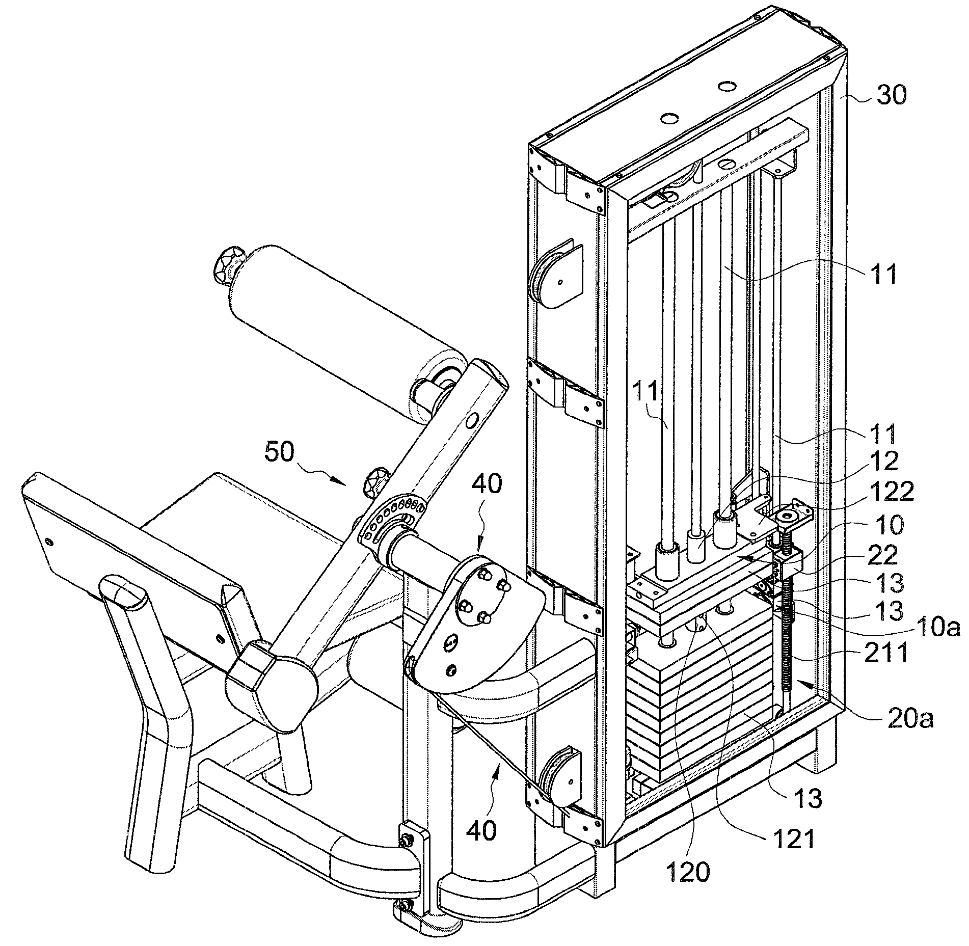
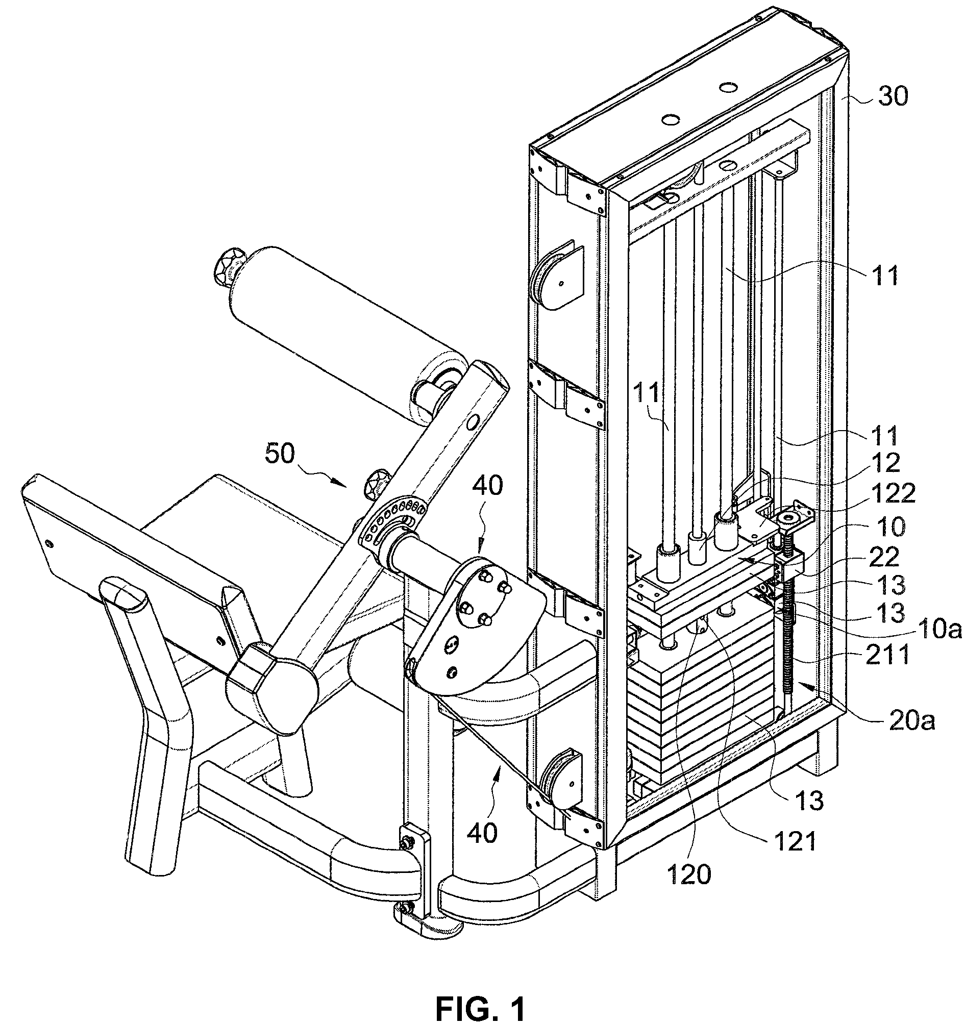
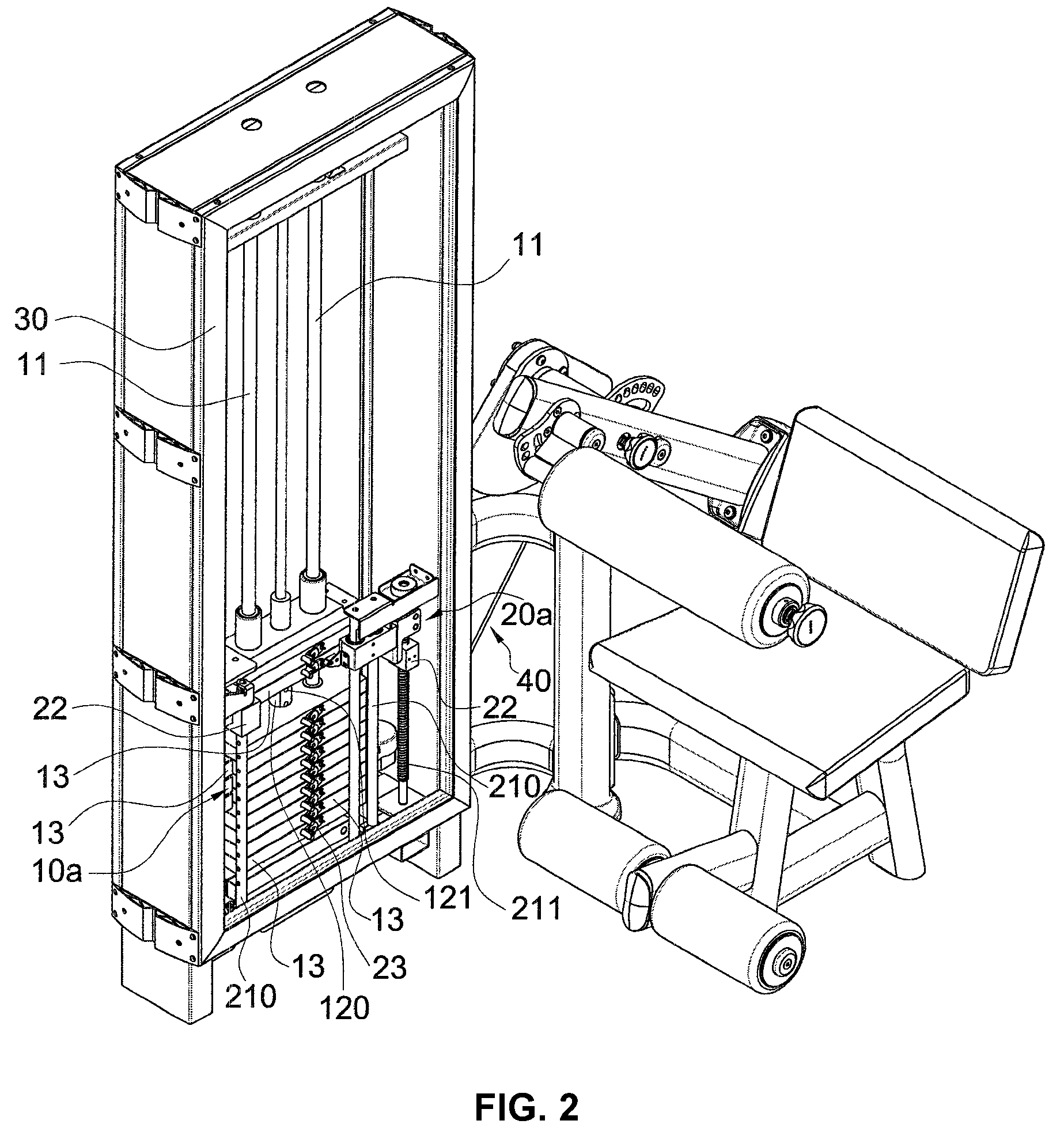
[0020]Referring to FIGS. 1 to 6, the adjustable weight assembly of the present invention comprises a weight device 10 and an adjustment device 20. The weight device 10 is connected to a base 30 and has at least one rail 11. A movable member 12 and multiple weights 13 are movably located on the rail 11. The movable member 12 is connected to a rod 120 and applied by a force from a force applying unit 40 of a weight training machine 50. The rod 120 has multiple through holes 121 defined therethrough. The user uses the force applying unit 40 to move the movable member 12 along the rail 11. Each weight 13 has a latitude hole 130 and a longitudinal hole 131 which communicates with the latitude hole 130. As shown in FIGS. 4 and 10, each latitude hole 130 has a pin 14 extending therethrough and the rod 120 extends through the longitudinal holes 131. The through holes 121 are located corresponding to the latitude holes 130. When the pin 14 is inserted into the through hole 121, the weight 13...


PUM


Abstract

An adjustable weight assembly includes a weight device and an adjustment device. The weight device includes a rail, a movable member and multiple weights. The movable member is connected to a rod and receives a force applied by a force applying unit so as to move along the rail. The rod has multiple through holes and each weight has a latitude hole and a longitudinal hole. Each latitude hole has a pin extending therethrough and the rod extends through the longitudinal holes. The adjustable device includes a driving unit, a movable part and multiple pivotal members. The driving unit drives the movable part and each weight is pivotably connected to one of the pivotal members. When the movable part moves along the rail, the pivotal member is pivoted to decide the engagement between the pin and the through hole so that the user can adjust the number of the weights.

Description

FIELD OF THE INVENTION[0001]The present invention relates to an adjustable weight assembly, and more particularly, to an adjustable weight assembly for a weight training machine.BACKGROUND OF THE INVENTION[0002]The conventional weight training machine provides proper number of weights to train the user's muscles by repeatedly lifting and lowering the weights. U.S. Pat. No. 6,551,223, U.S. Pat. No. 6,974,405 and U.S. Pat. No. 7,011,609 disclose a weight training machine which is has a rail on a base, and a movable member and multiple weights are movably installed to the rail. The movable member is connected to a rod and a force applying unit. The rod extends through the weights and has multiple holes. The weight is positioned by extending a pin through one of the holes. The user applies a force to the force applying device to move the movable member and the weights to achieve the purpose of training. However, the prior arts do not have linked pins to automatically choose the number o...

Claims


Application Information

Patent Timeline
Patent Type & Authority Patents(United States)
IPC IPC(8): A63B21/062
CPCA63B2021/0623A63B21/00065A63B21/062A63B21/0628A63B21/063
Inventor LO, CHIU-HSIANG
Owner LO CHIU HSIANG
Learn More