
Method for measuring propagation loss in a plane light guide plate

a technology of propagation loss and plane light, which is applied in the field of measurement methods, can solve the problems of reducing the efficiency of mass transfer of reactants, increasing the time and cost of processes, and reducing the efficiency of photocatalyst illumination area, so as to achieve the effect of research

Inactive Publication Date: 2014-07-01
NAT APPLIED RES LAB
View PDF16 Cites 0 Cited by
  • Summary
  • Abstract
  • Description
  • Claims
  • Application Information

AI Technical Summary

Benefits of technology

[0026]As mentioned above, the method for measuring propagation loss in a plane light guide plate in accordance with the present invention is of great importance to the photoelectric detection technology, as well as applications of chemical engineering, environmental engineering or other green technologies. The losses of the lights in different plane light guide plates can be measured directly by the method for measuring propagation loss in a plane light guide plate in accordance with the invention. Thus, the development of the applications of the plane light guide plate for photocatalysts or synergy of surface plasma is significantly accelerated and then the researches and the adding value thereof are improved.

Problems solved by technology

However, the photocatalysts are needed to be recycled from the reaction solution, and thus the complexity, time and costs of the processes increase.
Additionally, it is still doubted how to make the photocatalyst have sufficient illuminated area in order to carry out photocatalytic reaction for mass production.
As described in U.S. Pat. Nos. 5,875,384, 5,919,422 and 6,238,630, the efficiency of the reactions of the light-guided photocatalytic reactors with small volumes is good, but the reactors are required to fix in reaction tanks resulting in lower efficiency of mass transfer of reactants.

Method used


Image

  • Method for measuring propagation loss in a plane light guide plate
  • Method for measuring propagation loss in a plane light guide plate
  • Method for measuring propagation loss in a plane light guide plate

Examples


Embodiment Construction

[0035]The present invention is more specifically described in the following paragraphs by reference to the drawings attached only by way of examples. For convenience of understanding the principles of the invention, the same elements / components having same functions or structures in any of the following examples are marked as the same numbers or symbols.

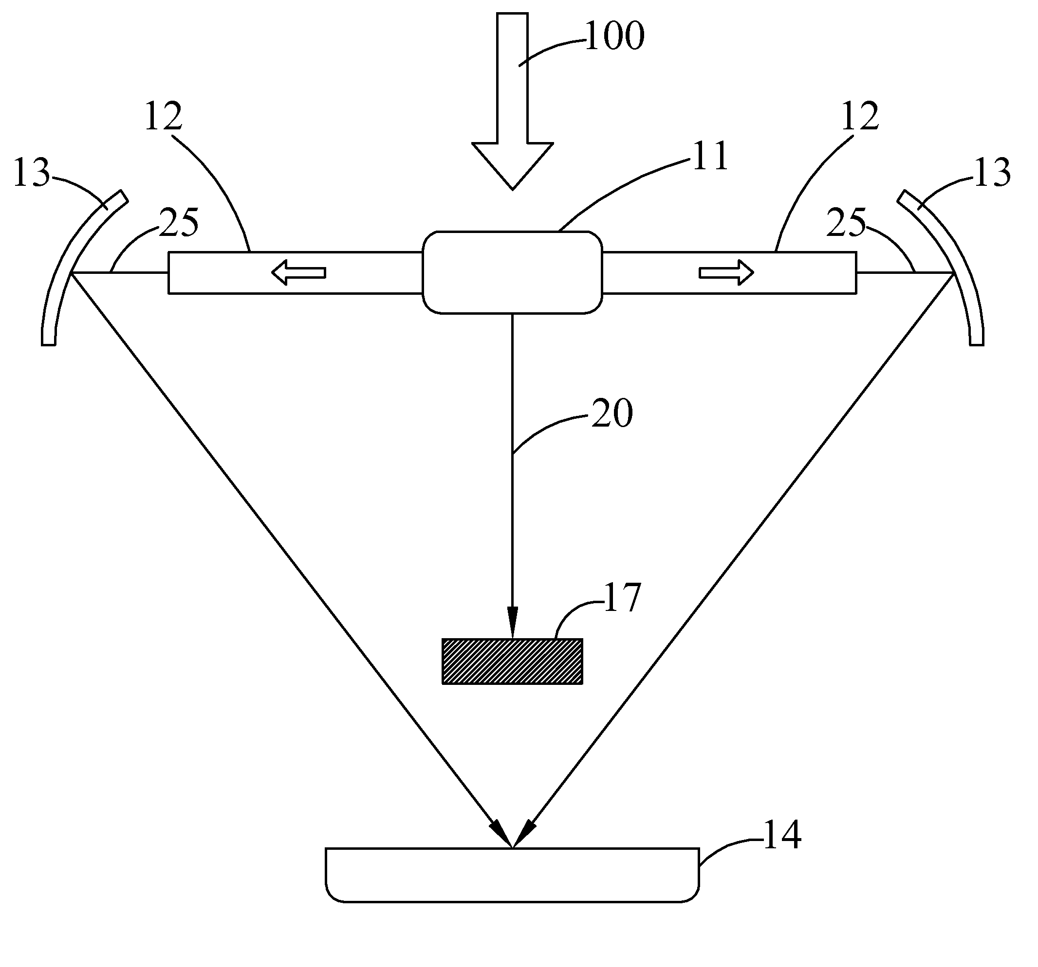
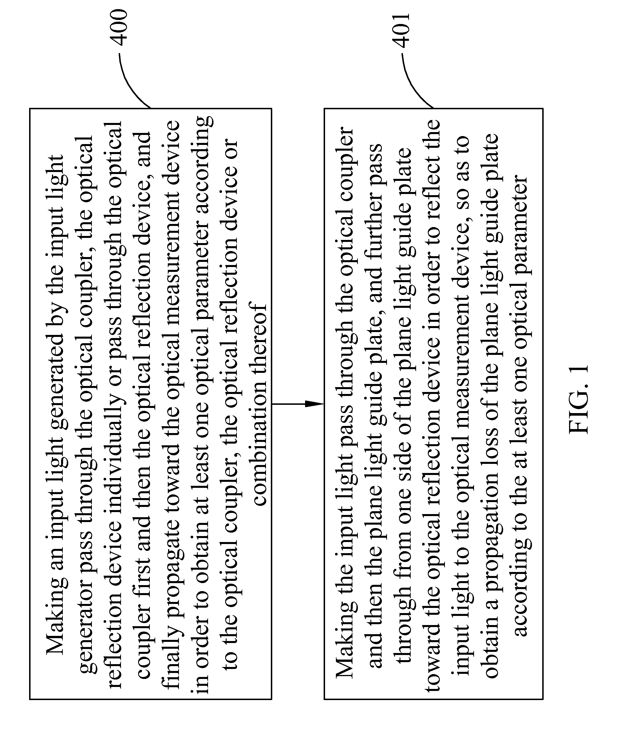
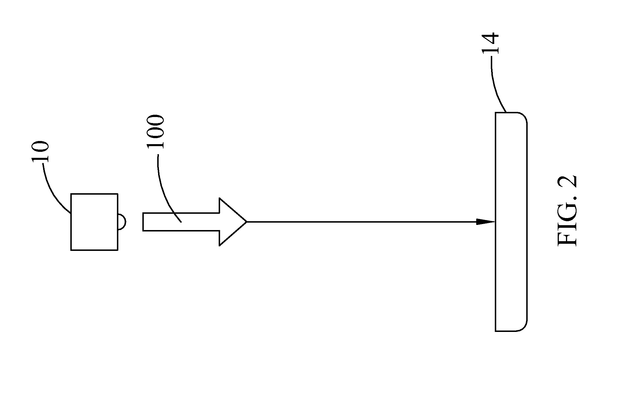
[0036]With reference to FIG. 1, it is a flow diagram of a method for measuring propagation loss in a plane light guide plate in accordance with the present invention. Such method for measuring propagation loss in a plane light guide plate can be used in a photocatalytic reactor, and the photocatalytic reactor can includes an input light generator, an optical coupler, a plane light guide plate, an optical reflection device and an optical measurement device. As shown in the figures, the method for measuring propagation loss in a plane light guide plate in accordance with the invention comprises steps of:

[0037]400: making an input light...


PUM

PropertyMeasurementUnit
angleaaaaaaaaaa
diameteraaaaaaaaaa
thicknessaaaaaaaaaa

Abstract

A method for measuring propagation loss in a plane light guide plate, which includes the following steps of making an input light generated by an input light generator pass through an optical coupler, an optical reflection device individually or pass through the optical coupler first and then the optical reflection device, and finally propagate toward an optical measurement device to obtain at least one optical parameter according to the optical coupler, the optical reflection device or the combination thereof; and making the input light pass through the optical coupler and then the plane light guide plate, and further pass through the plane light guide plate from one side thereof toward the optical reflection device in order to reflect the input light toward the optical measurement device, so as to obtain a propagation loss of the plane light guide plate according to the at least one optical parameter.

Description

CROSS-REFERENCE TO RELATED APPLICATION[0001]This application claims the benefit of Taiwan Patent Application No. 101123448, filed on Jun. 29, 2012, in the Taiwan Intellectual Property Office, the disclosure of which is incorporated herein in its entirety by reference.BACKGROUND OF THE INVENTION[0002]1. Field of the Invention[0003]The present invention relates to a measurement method, and particularly a method for measuring propagation loss in a plane light guide plate.[0004]2. Description of the Related Art[0005]Optical plane light guide plates are of great importance to application of optical technology, especially of the field in opto-electronic display. Such issues are discussed in US Patent Publication No. 2005 / 0084228 A1, US Patent Publication No. 2009 / 0316072 A1US Patent Publication No. 2011 / 0069510 A1 and U.S. Pat. No. 7,325,960 B2. Recently, optical plane light guide plates are used in chemical reactors of photocatalysts, as driving elements in the chemical reactors or in pl...

Claims


Application Information

Patent Timeline
Patent Type & Authority Patents(United States)
IPC IPC(8): G01N21/00
CPCG01N21/59G01M11/30G01M11/00G02B6/00
Inventor TSAI, DIN PINGHUANG, KUO-CHENGHUANG, HUNG JI
Owner NAT APPLIED RES LAB
Learn More