
Doppler tracking in presence of vehicle velocity uncertainty

a technology of uncertainty and velocity, applied in the direction of speed/acceleration/shock measurement, measurement devices, instruments, etc., can solve the problem of uncertainty in the velocity measurement data associated with an ins, and achieve the effect of erroneous velocity results

Active Publication Date: 2014-07-01
RAYTHEON CO
View PDF26 Cites 0 Cited by
  • Summary
  • Abstract
  • Description
  • Claims
  • Application Information

AI Technical Summary

Benefits of technology

This approach ensures accurate tracking of relative velocity between a vehicle and a target by correcting for velocity measurement uncertainties, maintaining a lock on the target, and providing precise velocity data despite laser motion uncertainties.

Problems solved by technology

There is, however, uncertainty in the velocity measurement data associated with an INS.
The uncertainty can result in the laser return being lost or can result in the system tracking an adjacent frequency to the true frequency of the laser, thereby yielding erroneous velocity results.

Method used


Image

  • Doppler tracking in presence of vehicle velocity uncertainty
  • Doppler tracking in presence of vehicle velocity uncertainty
  • Doppler tracking in presence of vehicle velocity uncertainty

Examples


Embodiment Construction

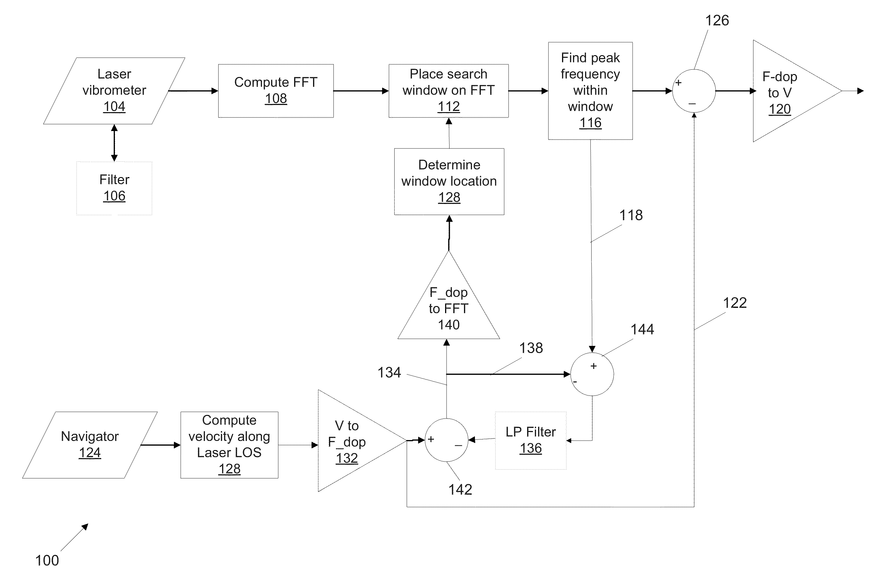
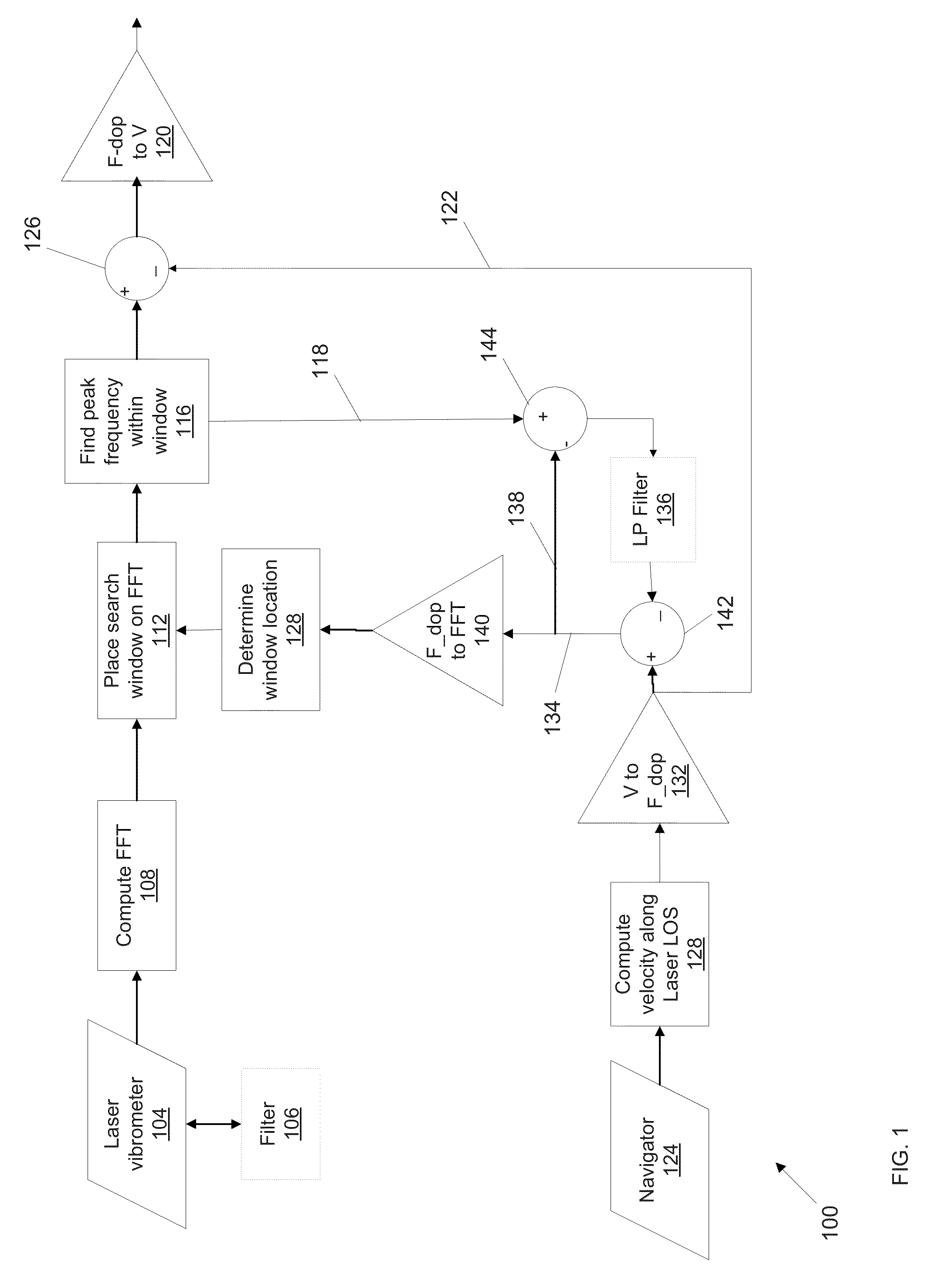
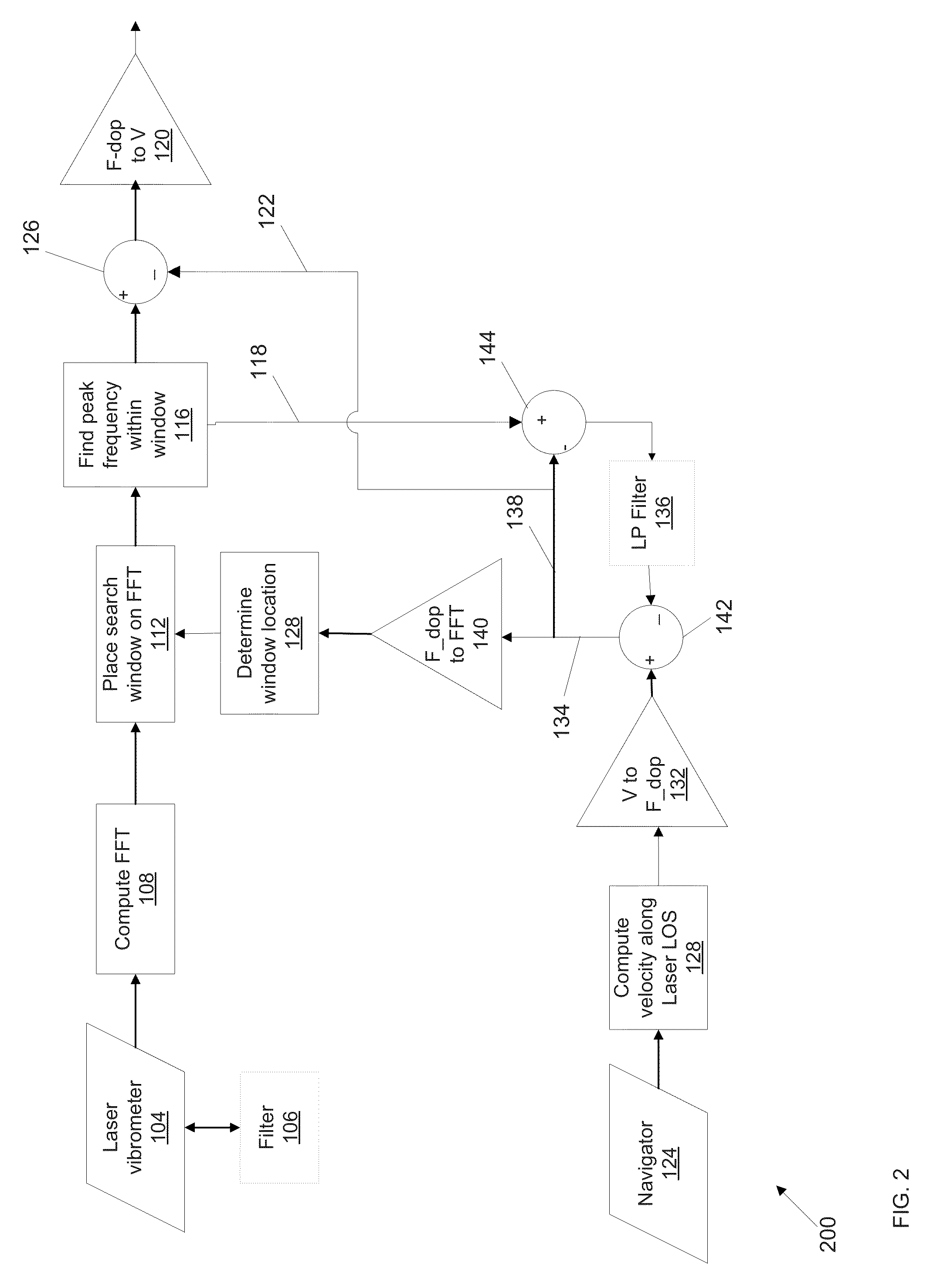
[0016]FIG. 1 is a flowchart 100 of a method for tracking the relative velocity between a vehicle (or some other moving system) and a target, according to an illustrative embodiment. The velocity of the vehicle, relative to the target, is determined (output of step 120) by the method described further below. The vehicle includes a laser vibrometer and an inertial navigation system (also referred to as a navigator). A laser vibrometer (also referred to as a vibrometer or laser Doppler vibrometer) is an instrument used to perform non-contact vibration measurements of a surface. A vibrometer typically generates two laser beams, an internal reference laser beam and a test beam. The test beam is directed to the surface of interest. The vibrometer measures the frequency difference (or equivalently, phase difference) between the internal reference laser beam and the test beam return signal. The laser vibrometer output is typically an analog voltage signal that is proportional to the relativ...


PUM


Abstract

Methods for tracking the relative velocity between a vehicle and a target that uses both a measured velocity as well as an estimate of the velocity that is based on tracking the peaks in a laser vibrometer return signal.

Description

GOVERNMENT SUPPORT[0001]The invention was supported, in whole or in part, by a grant, Grant No. W909MY-07-C-0018, from the Department of Defense. The Government has certain rights in the invention.BACKGROUND[0002]Laser vibrometers measure the relative velocity between the laser and a target by measuring the Doppler frequency shift of the laser return from the target. The motion of the laser can affect the accuracy of the velocity measurement. A need therefore exists for improved methods and systems for tracking the relative velocity between a laser vibrometer and a target.SUMMARY[0003]The technology described herein relates to the use of a laser vibrometer for measuring the relative velocity between the laser and a target that involves measuring the Doppler frequency shift of the laser return from the target. Because the motion of the laser can be larger than the target motion, an inertial navigation system (INS) is used to measure the laser motion. There is, however, uncertainty in...

Claims


Application Information

Patent Timeline
Patent Type & Authority Patents(United States)
IPC IPC(8): G01P3/36G01S17/86G01S17/931
CPCG01S17/023G01S17/936G01S17/58G01S7/497G01P3/36G01H9/002G01S17/86G01S17/931
Inventor SHIMON, PHILIP T.PRAGER, KENNETH E.LEWINS, LLOYD J.
Owner RAYTHEON CO
Learn More