
Air duct system for vehicles, in particular for rail vehicles for passenger traffic

a technology for air duct systems and vehicles, which is applied in vehicle components, railway heating/cooling, vehicle heating/cooling devices, etc., can solve problems such as noise generation and flow speed, and achieve the effects of reducing noise generation, increasing flow rate, and increasing noise generation

Inactive Publication Date: 2014-07-01
SIEMENS AG
View PDF14 Cites 3 Cited by
  • Summary
  • Abstract
  • Description
  • Claims
  • Application Information

AI Technical Summary

Benefits of technology

This solution reduces flow speed and noise generation, enabling the same duct cross-section to handle different climatic zones with varying air flow rates, reducing design, mounting, and logistics costs while meeting customer requirements flexibly.

Problems solved by technology

As a result, the flow speed and the generation of noise drop.

Method used


Image

  • Air duct system for vehicles, in particular for rail vehicles for passenger traffic
  • Air duct system for vehicles, in particular for rail vehicles for passenger traffic
  • Air duct system for vehicles, in particular for rail vehicles for passenger traffic

Examples


Embodiment Construction

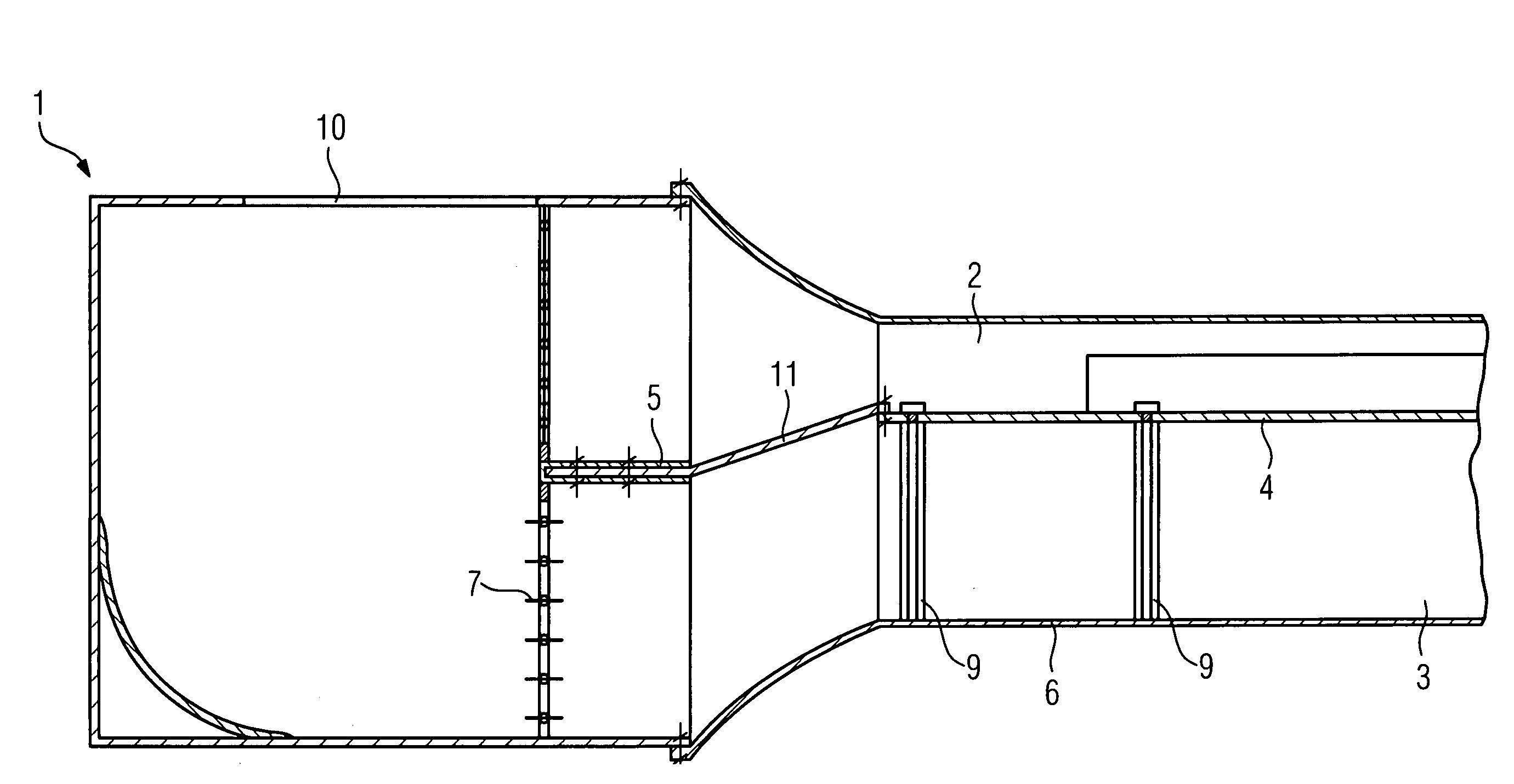
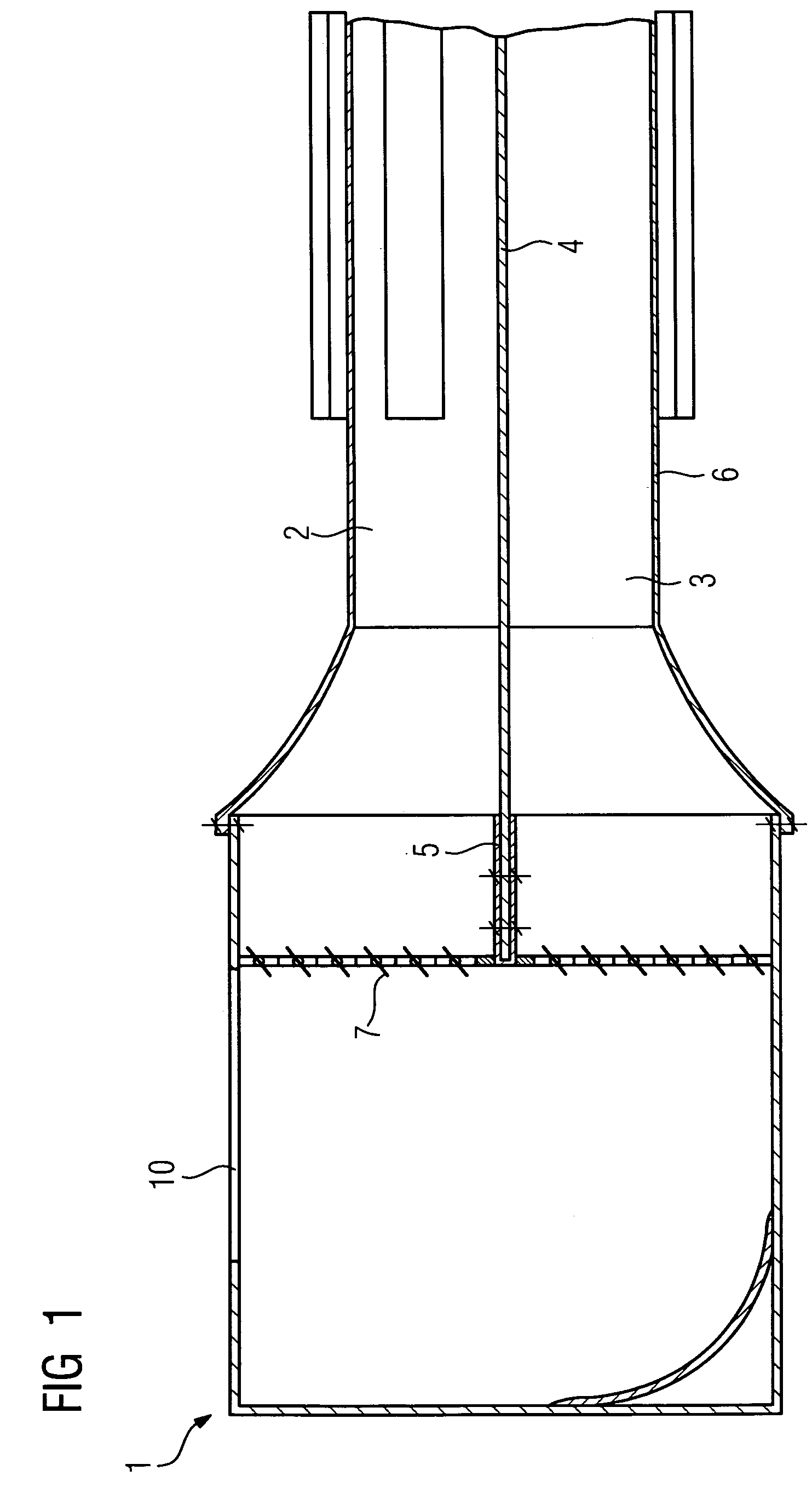
[0014]The air feed is blown out by an air-conditioning device (not illustrated here) and is intended to pass into the passenger compartment via an air duct system which is arranged in the roof area of the vehicle. According to FIGS. 1 and 4, for this purpose this air is firstly fed to a roof venting duct 1 via an air inlet 10 and is conducted by means of adjustable flaps 7 into a component venting duct 2 for warm air and / or into a component venting duct 3 for cold air. FIG. 1 illustrates the possibility of setting the flaps 7 in such a way that both component venting ducts 2 and 3 are supplied with air. In the exemplary embodiment according to FIG. 4, the flaps 7 are set in such a way that they clear the selected component venting duct 3 for cold air and close the component venting duct 2, which is not acted on, for warm air.

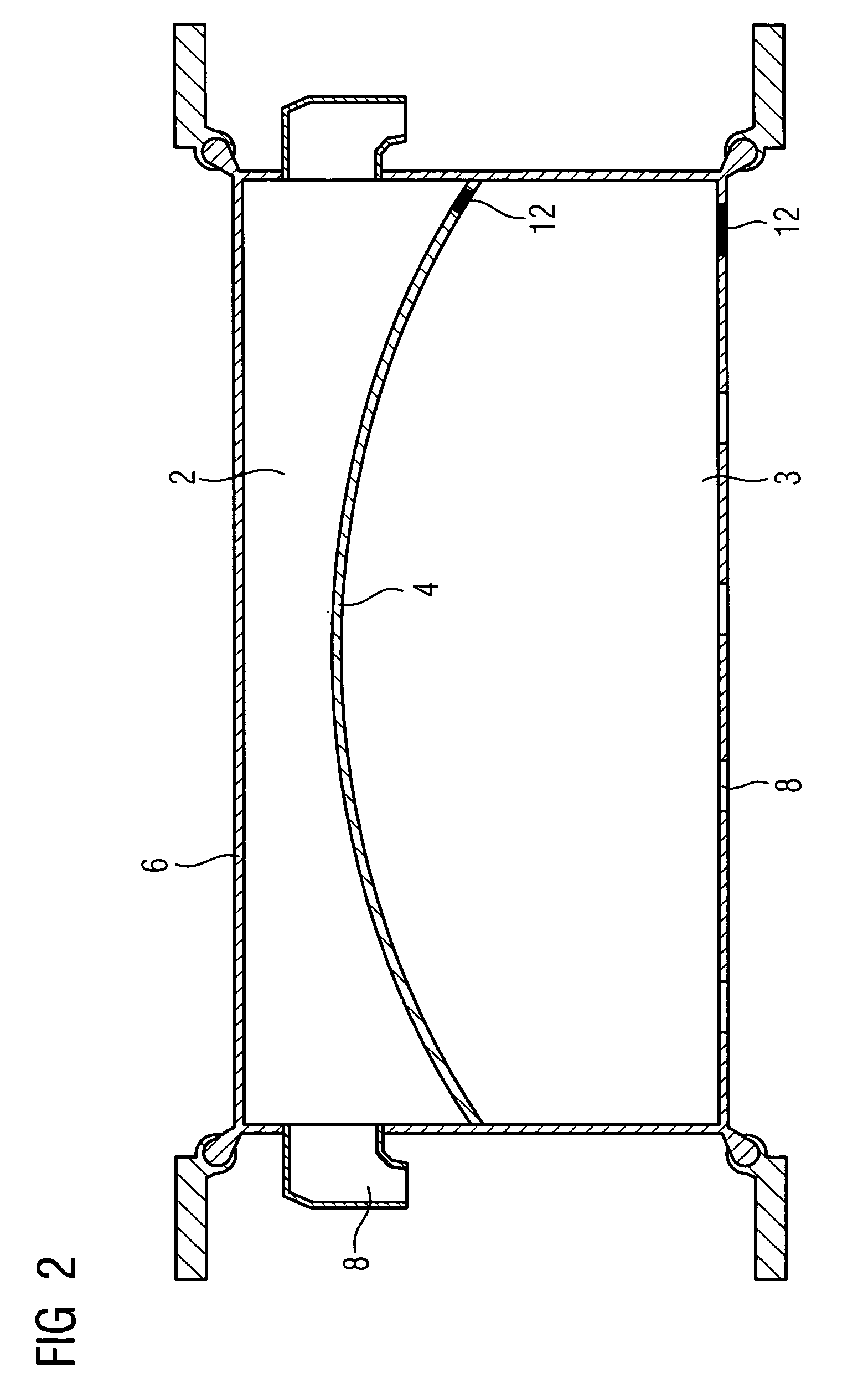
[0015]The air duct system according to FIGS. 1, 2 and 3 contains on the inside a deformable separating means 4 which is embodied as an airtight textile separati...


PUM


Abstract

An air duct system for vehicles, in particular for passenger rail vehicles, has at least one roof venting duct, which has a component venting duct for warm air and a component venting duct for cold-air. A separating means which is arranged inside the roof venting duct is designed so it can be deformed or is held in a movable fashion in such a way that the cross section of each of the two component venting ducts can be enlarged by making the respective other component venting duct smaller. These changes in cross section are brought about solely by the air pressure and volume flow conditions without external energy.

Description

CROSS REFERENCE TO RELATED APPLICATIONS[0001]This application is the US National Stage of International Application No. PCT / EP2006 / 063129, filed Jun. 13, 2006 and claims the benefit thereof. The International Application claims the benefits of German application No. 10 2005 031 912.2 filed Jul. 7, 2005, both of the applications are incorporated by reference herein in their entirety.FIELD OF INVENTION[0002]The invention relates to an air duct system for vehicles, in particular for rail vehicles for passenger traffic, having at least one roof venting duct which has a component venting duct for warm air and a component venting duct for cold air.BACKGROUND OF THE INVENTION[0003]Devices for distributing air are generally known in air conditioned rail vehicles with air conditioning systems which are mounted in the roof area. In these devices, the treated air is fed from the air conditioning system, frequently arranged on the roof of the vehicle, to main venting ducts using air feed ducts,...

Claims


Application Information

Patent Timeline
Patent Type & Authority Patents(United States)
IPC IPC(8): B61D27/00
CPCB60H1/00564B60H1/262B61D27/0018
Inventor HOFLER, WERNERWICHMANN, RAINER
Owner SIEMENS AG
Learn More