
Metropolitan IP aggregation network design tool

a technology of aggregation network and tool, applied in the field of communications network design, can solve the problems of large and complex design problem of networks, and achieve the effect of reducing the total cost including fiber cost and network backbone packet switch cos

Inactive Publication Date: 2014-06-10
AT&T INTPROP I L P
View PDF0 Cites 13 Cited by
  • Summary
  • Abstract
  • Description
  • Claims
  • Application Information

AI Technical Summary

Benefits of technology

The tool described in this patent helps planners to efficiently design networks using access packet switches and core backbone switches. It selects the most cost-effective location for switches based on network facility locations and calculates the fiber cost of diverse paths. It also allows for easy design changes and sensitivity analysis studies. The tool is faster and more flexible than previous methods, making the design process more efficient and flexible. The technical effects of this tool include reducing fiber costs, using lower-cost Ethernet optics, and improving network design flexibility.

Problems solved by technology

The networks present a large and complex design problem.

Method used


Image

  • Metropolitan IP aggregation network design tool
  • Metropolitan IP aggregation network design tool
  • Metropolitan IP aggregation network design tool

Examples


Embodiment Construction

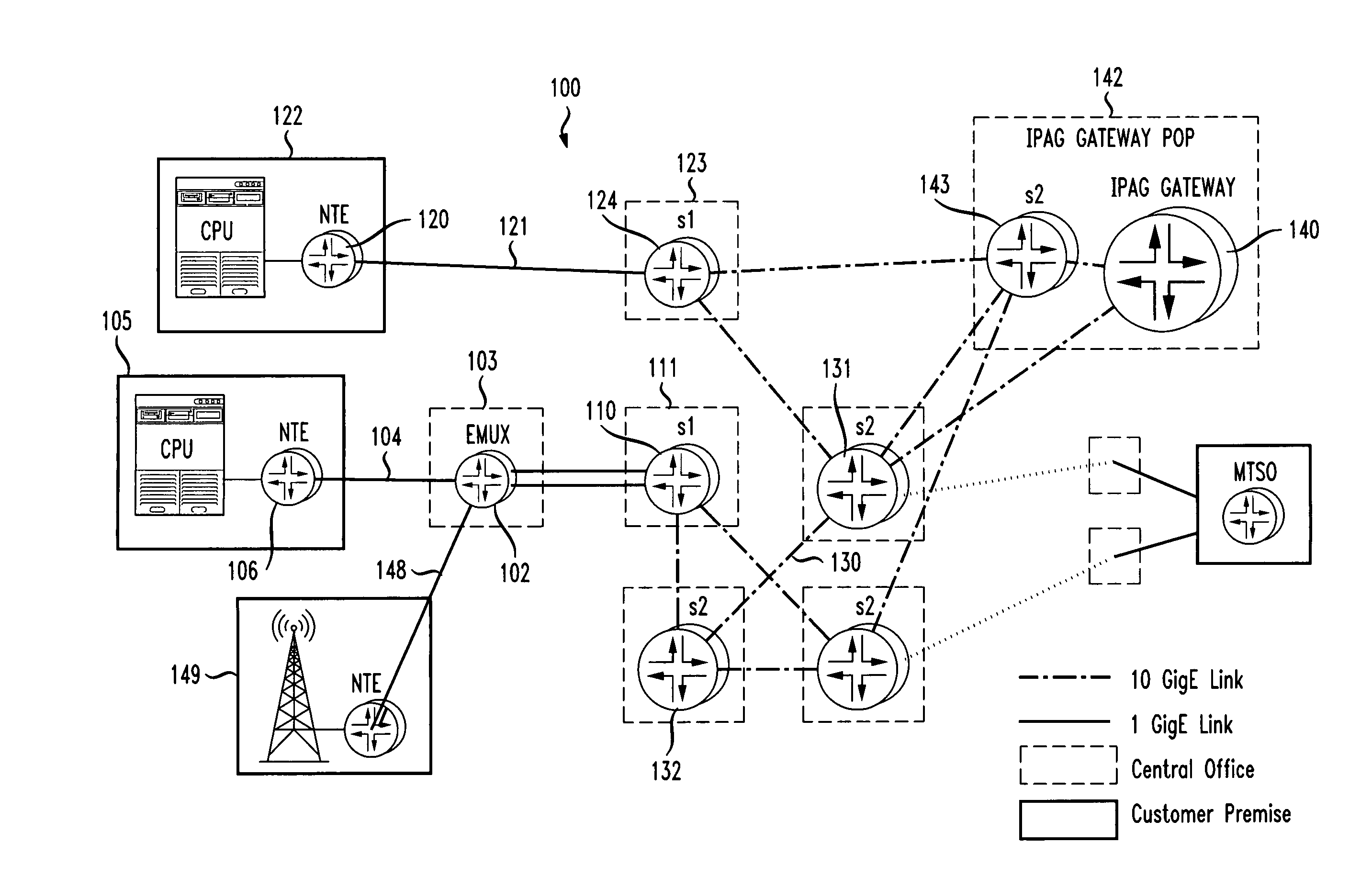
[0022]Embodiments of the disclosure will be described with reference to the accompanying drawing figures wherein like numbers represent like elements throughout. Before embodiments of the disclosure are explained in detail, it is to be understood that the disclosure is not to be limited in its application to the details of the examples set forth in the following description and / or illustrated in the figures. The disclosure is capable of other embodiments and of being practiced or carried out in a variety of applications. Also, it is to be understood that the phraseology and terminology used herein is for the purpose of description and should not be regarded as limiting. The use of “including,”“comprising,” or “having” and variations thereof herein is meant to encompass the items listed thereafter and equivalents thereof as well as additional items.

[0023]The methods disclosed below may be implemented by program modules that are executed by a computer. Generally, program modules inclu...


PUM


Abstract

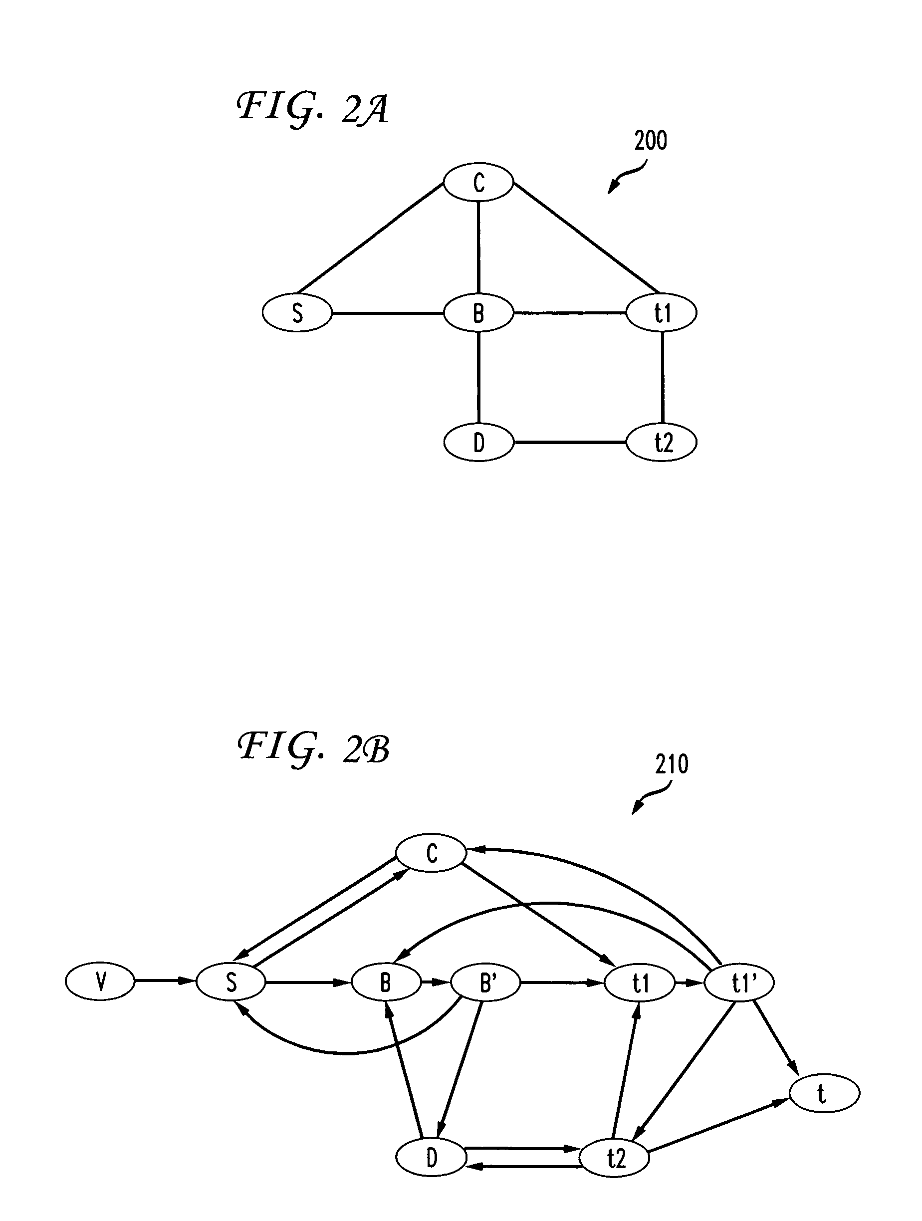
In a tool for use by network planners in designing metropolitan IP aggregation networks, several optimization methods are integrated into a tool. A k-means algorithm is used to choose access packet switch locations. A dual-k-means algorithm is used to choose the backbone switch locations. Each access packet switch is dual homed to two backbone packet switches using two diverse paths. The diverse path configuration is found using a maxflow-mincost algorithm on a modified fiber map topology. The link topology connecting the backbone packet switches to each other is designed using a heuristic that creates a skeleton network topology and then adds express links one by one, testing each link to assure reduced overall network cost. The resulting network topology is then improved upon by local search.

Description

FIELD OF THE DISCLOSURE[0001]The present disclosure relates generally to the design of communications networks, and more particularly, to tools for designing an aggregation network including both network access packet switches and network backbone packet switches.BACKGROUND[0002]New IP aggregation (“IPAG”) networks use a layered architecture, including OSI Layer-2 (L2) aggregation or access packet switches, connected by physically diverse fiber paths to a “cluster” of IPAG core network backbone packet switches. Layer-2 is a protocol layer in the Open Systems Interconnection (OSI) protocol stack and includes protocols such as Ethernet VLAN (Virtual Local Area (LAN) Network) and Multiprotocol Label Switching (MPLS). The term “IP aggregation” represents the idea that Ethernet frames, including IP packets, are collected on the edge of the IPAG network and then, for network efficiency and compatibility with typical enterprise LANs, encapsulated into L2 protocol data units and then routed...

Claims


Application Information

Patent Timeline
Patent Type & Authority Patents(United States)
IPC IPC(8): H04L12/28
CPCH04L12/28H04L45/12H04W40/02H04L45/64
Inventor MATTHEWS, DAVIDBHAGAT, PROMOD KUMARDOVERSPIKE, ROBERT DUNCANKLINCEWICZ, JOHN GREGORYLI, JIANLI, GUANGZHILYNCH, DAVID FREDERICKSEGAL, MOSHEWANG, DONGMEI
Owner AT&T INTPROP I L P
Learn More