
Drive pin assembly

Active Publication Date: 2014-05-27
CWD
View PDF9 Cites 2 Cited by
  • Summary
  • Abstract
  • Description
  • Claims
  • Application Information

AI Technical Summary

Benefits of technology

The invention provides drive pin assemblies and methods for their use that are both effective and easy to implement. This solves the problem of difficulty in implementing effective methods.

Problems solved by technology

However, each has its own drawbacks, e.g., in terms of ability to securely attach the drive pin to the wheel hub, difficulty of installation, complexity, cost, size, etc.

Method used


Image

  • Drive pin assembly
  • Drive pin assembly
  • Drive pin assembly

Examples


Embodiment Construction

)

[0018]The present invention concerns drive pin assemblies, e.g., of the type that may be used to attach a disc brake rotor to a hub (e.g., for use in an automobile or any other motorized vehicle), as well as to components of such assemblies and methods for using such assemblies and / or components. However, it should be noted that the drive pin assemblies according to the present invention also may be used in any of a variety of other situations.

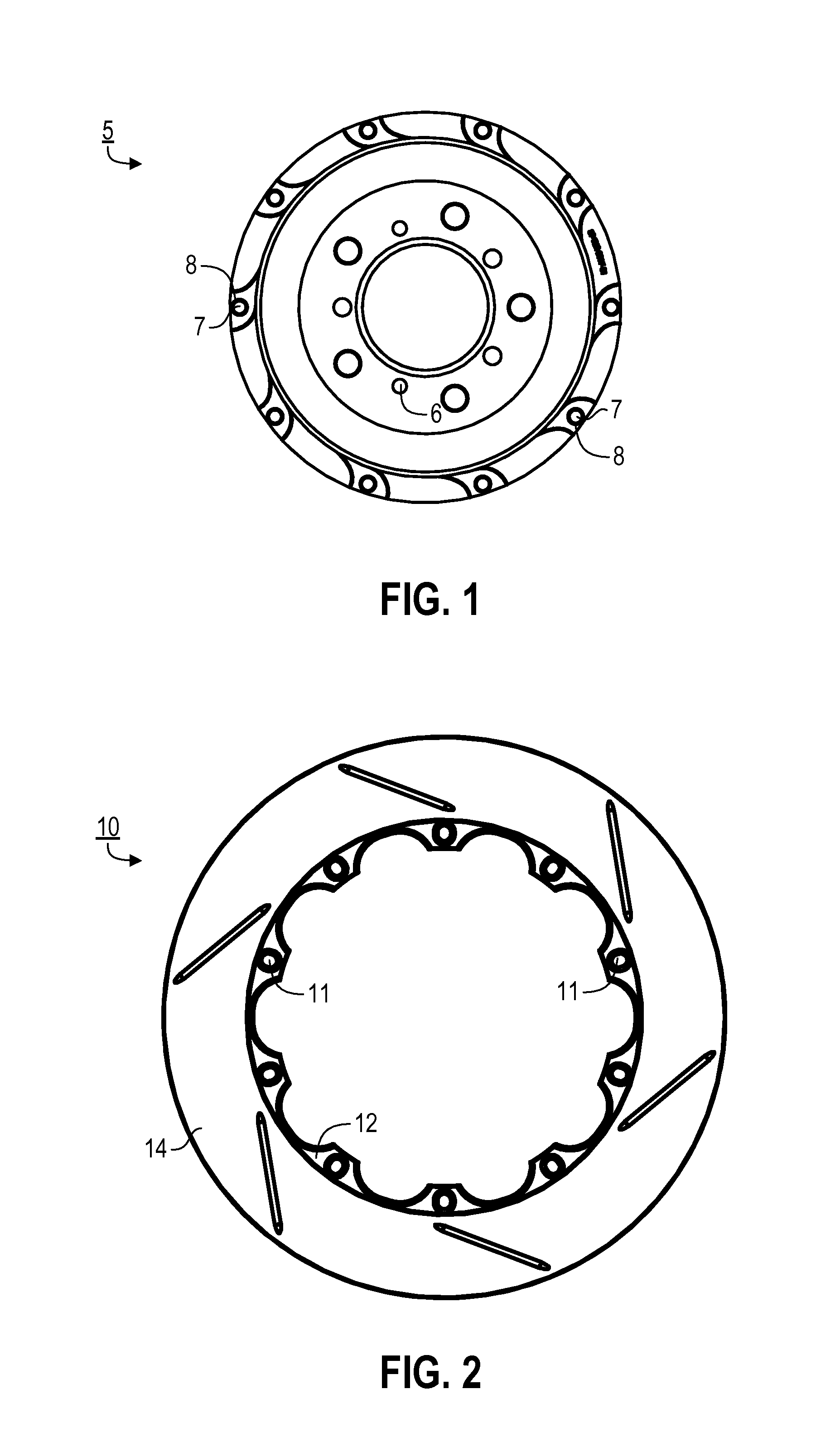
[0019]FIG. 1 illustrates a hub (or hat) 5 that is attached to an axle or a wheel drive assembly of a motorized vehicle (e.g., through openings 6) when in use. One of the purposes of hub 5 is to function as a mounting element for attaching a disc brake rotor. Included in hub 5 is a ring of circular openings (or through-holes) 7, each defined by a sidewall 8, for this purpose.

[0020]FIG. 2 illustrates a disc brake rotor 10 to be attached to hub 5. A ring of openings (or through-holes) 11 are provided within a mounting section 12 (or ring) of rot...


PUM


Abstract

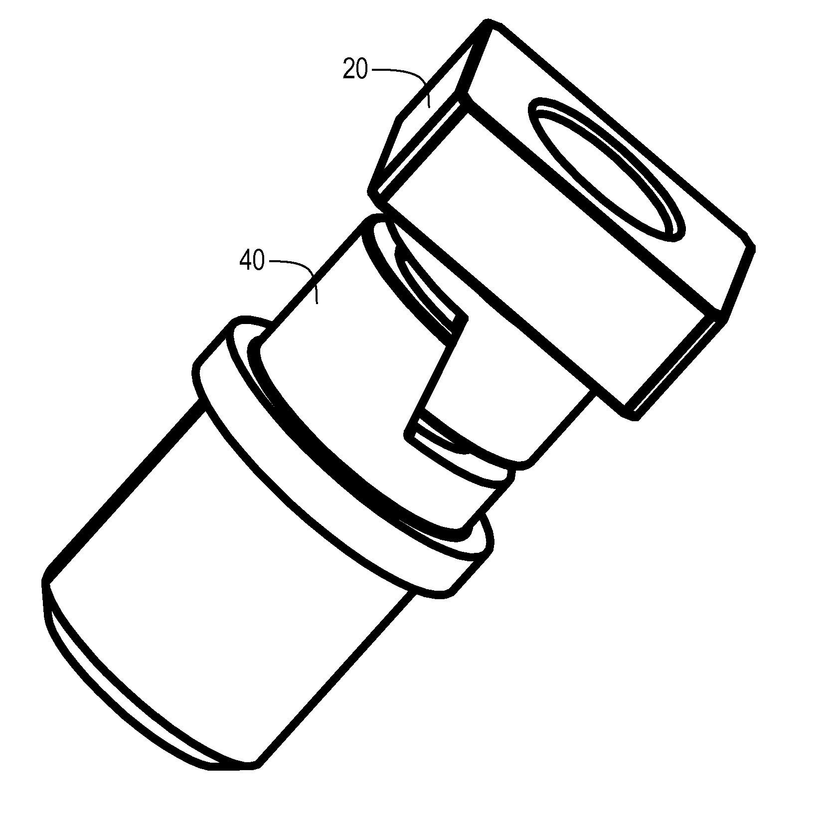
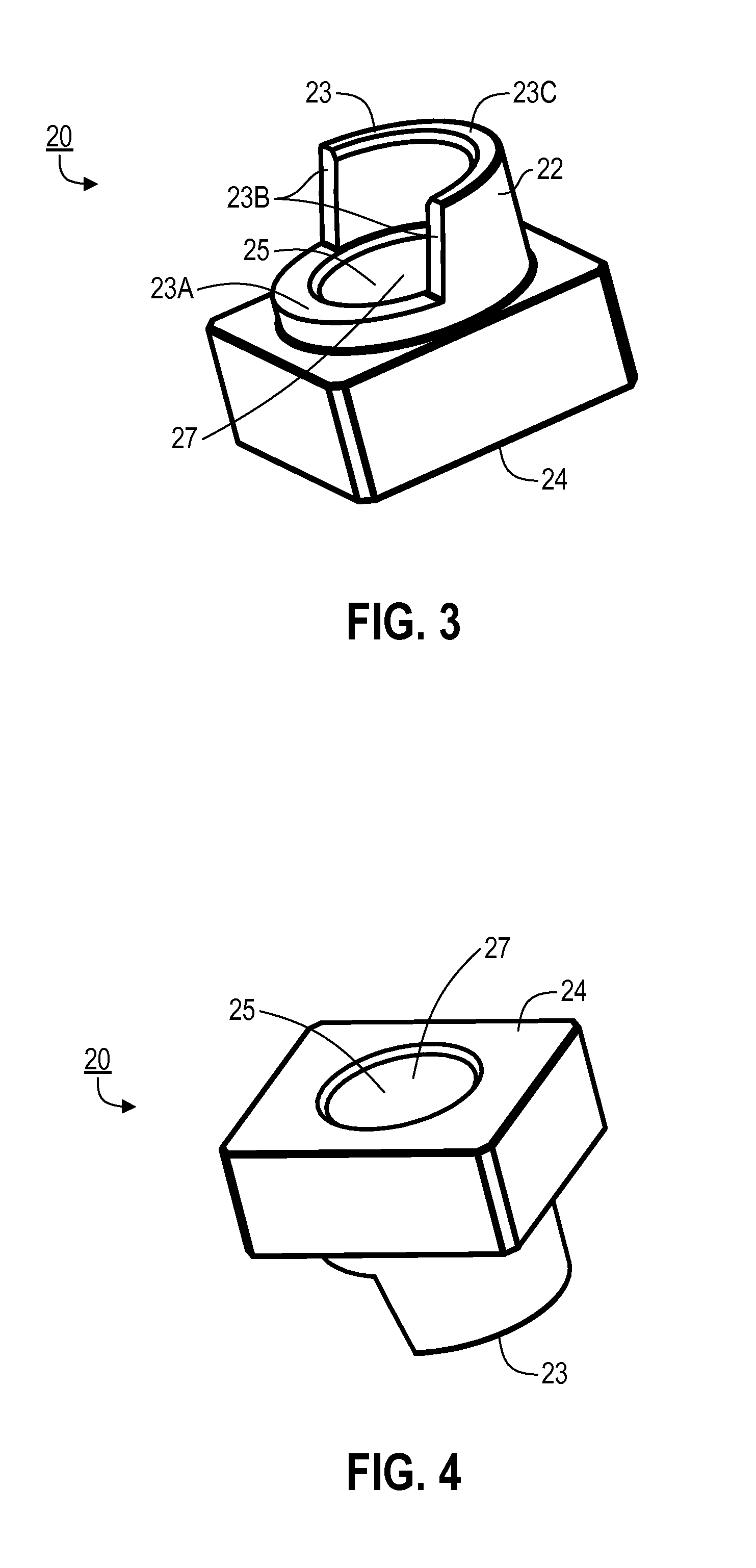
Provided are, among other things, systems, apparatuses, components and methods related to drive pin assemblies. One such assembly includes: a first pin component and a second pin component, each having an engagement end that opens to an interior space and has an angled surface that extends for at least a portion of the width and a portion of the length of such first pin component; and a tightening mechanism at least partially disposed within the interior spaces of the first pin component and the second pin component, for drawing the first pin component and the second pin component closer together, where the angled surface of the first pin component matches the angled surface of the second pin component such that the first pin component and the second pin component slide both vertically and laterally along each other when drawn together.

Description

FIELD OF THE INVENTION[0001]The present invention pertains to drive pin assemblies, such as might be used for securing a disc brake rotor to a hub.BACKGROUND[0002]For the purpose of attaching a disc brake rotor to a wheel hub, it often is desirable to provide a series of equally spaced openings through a mounting ring on the rotor, with such openings being elongated in the radial direction. The rotor can then be attached to the hub using “drive pins” that extend through such openings. An advantage of attaching a rotor in this way is to accommodate radial expansion and contraction of the rotor as it heats and cools, respectively. A variety of different drive pin configurations currently exist. However, each has its own drawbacks, e.g., in terms of ability to securely attach the drive pin to the wheel hub, difficulty of installation, complexity, cost, size, etc.SUMMARY OF THE INVENTION[0003]The present invention addresses these problems by providing drive pin assemblies, components th...

Claims


Application Information

Patent Timeline
IPC IPC(8): F16D65/02F16D65/12
CPCF16D2065/1316F16B19/00F16D2065/1392F16D2065/1328F16D65/12
Inventor RUIZ, STEPHEN, JOHN
Owner CWD
Learn More