Plasma ignition system, plasma ignition method, and plasma generating apparatus

a technology of plasma generating apparatus and ignition system, which is applied in the direction of electric variable regulation, process and machine control, instruments, etc., can solve the problems of many products such as semiconductor circuits, defects that are developed in many products, and plasma often becomes unstable or disappears, etc., to achieve easy and reliable ignition

Active Publication Date: 2014-05-06
SHINKAWA CO LTD
View PDF32 Cites 6 Cited by
  • Summary
  • Abstract
  • Description
  • Claims
  • Application Information

AI Technical Summary

Benefits of technology

[0011]However, in the plasma generating apparatus, plasma often becomes unstable or disappears when a flow of an inert gas for plasma deteriorates or such. If plasma is unstable or disappears, defects are developed in many of products such as semiconductor circuits. Such defects can further result in disadvantageous effects such as heat generation at a section that is not the defective section. Taking time before the disappearance of plasma is found results in defects developed in many products. Therefore, the plasma generating apparatus disclosed in Patent Documents described above requires monitoring of the presence of plasma. Further, when the plasma has disappeared, it is necessary to manually reignite plasma. In addition, as it is necessary to conduct plasma ignition work with proper timing in parallel with application work for a high frequency power, a certain level of skill is required for the igniting work.
[0012]Thus, an object of the present invention, conceived in view of the above problems, is to provide a plasma ignition technique allowing easy and reliable ignition and reignition of plasma without monitoring or manual handling.Means For Solving the Problems
[0013]In order to address the above problem, a plasma ignition system according to the present invention is provided with: a radio-frequency power supply configured to supply a predetermined high frequency signal to an applied electrode for generating plasma; a matching device configured to match impedance on a side of the radio-frequency power supply and impedance on a side of the applied electrode; a forward wave / reflected wave detector configured to detect a forward wave and a reflected wave of the high frequency signal; a high-voltage generator configured to generate a predetermined high voltage; and a controller configured to superimpose the high voltage on the high frequency signal when a ratio of the reflected wave to the forward wave is greater than a first threshold value.
[0014]According to this configuration, when the high frequency signal is supplied to the applied electrode, the impedance on the side of the applied electrode is determined according to a state of the plasma at this time. If the plasma is not appropriately generated at this time, output impedance on a side of the matching device and the impedance on the side of the applied electrode do not match, and therefore the ratio of the reflected wave to the forward wave of the high frequency signal increases. When the ratio of the reflected wave to the forward wave is increased to some extent, it is estimated to be in a state before the ignition, or in a state in which the plasma that has once ignited has disappeared for some reason. Therefore, it is determined that plasma is not ignited if this ratio is greater than the first threshold value that is previously set in order to estimate the state in which the plasma has disappeared, and the high voltage is superimposed on the high frequency signal. By the high voltage, a discharge is generated to the applied electrode, and plasma is ignited or reignited.
[0015]In general, “a ratio of a reflected wave to a forward wave” is understood as a ratio of an amplitude value of the reflected wave to an amplitude value of the forward wave, for example, a standing wave ratio (SWR (Standing Wave Ratio) value).Effects of the Invention
[0016]According to the present invention, as a state of plasma ignition is determined based on a ratio of a reflected wave to a forward wave and then the igniting work is conducted, it is possible to easily and reliably ignite and reignite plasma without monitoring or manual handling.

Problems solved by technology

However, in the plasma generating apparatus, plasma often becomes unstable or disappears when a flow of an inert gas for plasma deteriorates or such.
If plasma is unstable or disappears, defects are developed in many of products such as semiconductor circuits.
Such defects can further result in disadvantageous effects such as heat generation at a section that is not the defective section.
Taking time before the disappearance of plasma is found results in defects developed in many products.
Further, when the plasma has disappeared, it is necessary to manually reignite plasma.

Method used


Image

  • Plasma ignition system, plasma ignition method, and plasma generating apparatus
  • Plasma ignition system, plasma ignition method, and plasma generating apparatus
  • Plasma ignition system, plasma ignition method, and plasma generating apparatus

Examples


embodiment 1

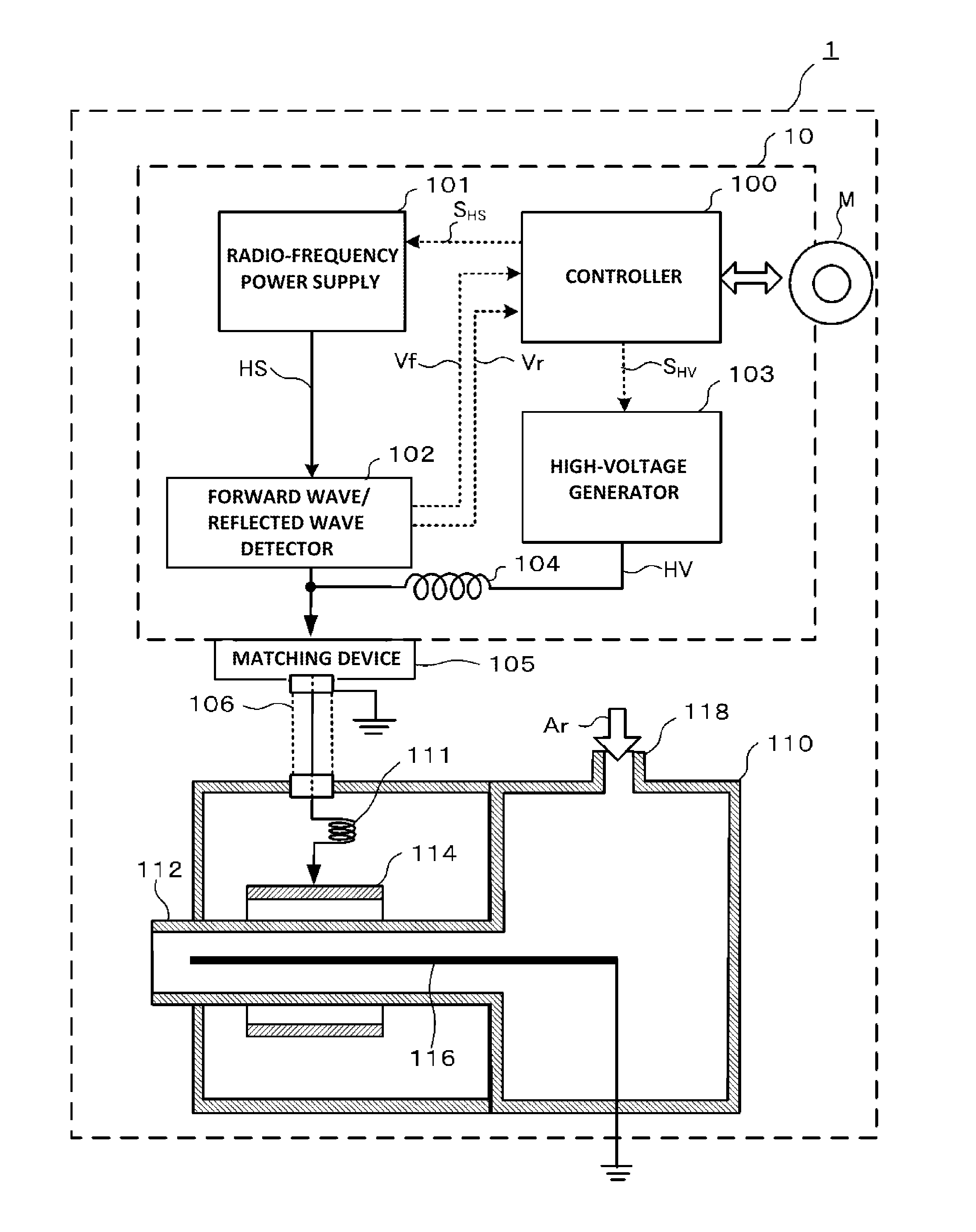
[0029]An embodiment 1 according to the present invention relates to a basic configuration of a plasma ignition system capable of automatically igniting plasma, and configured to superimpose a high voltage on a high frequency signal when a ratio of a reflected wave to a forward wave is greater than a predetermined threshold value, and to stop superimposing the high voltage when the ratio of the reflected wave to the forward wave becomes equal to or smaller than a threshold value after the high voltage is superimposed on the high frequency signal.

[0030]FIG. 1 shows a configuration diagram of a plasma generating apparatus including a plasma ignition system according to this embodiment. When used in the manufacturing of semiconductor circuits, a plasma generating apparatus 1 is disposed facing a cleaning surface of a semiconductor circuit as a cleaning target (bonding target), and used to generate plasma to clean the cleaning surface of the semiconductor circuit.

[0031]Referring to FIG. ...

embodiment 2

[0065]The embodiment 2 according to the present invention is an improvement of the embodiment 1, and relates to a case in which the threshold value (first threshold value) to start supplying a high voltage for igniting plasma and the threshold value (second threshold value) to stop supplying the high voltage are different.

[0066]Configurations of the plasma generating apparatus 1 and the plasma ignition system 10 according to the embodiment 2 are the same as those according to the embodiment 1, and explanations for these configurations will be omitted. However, the embodiment 2 is different from the embodiment 1 in that the program process by the controller 100 corresponds a flowchart in FIG. 4.

[0067]In the embodiment 2, the controller 100 operates so as to superimpose the high voltage HV on the high frequency signal HS when the VSWR value is greater than a first threshold value Vth1, and stop superimposing the high voltage HV when the VSWR value becomes equal to or smaller than a se...

embodiment 3

[0080]An embodiment 3 according to the present invention is an improvement of the embodiment 1, and relates to a case of outputting a predetermined alarm signal and stopping superimposing the high voltage in a case in which the VSWR value remains greater than the predetermined threshold value Vth when a first time period elapses after the high voltage is superimposed on the high frequency signal. According to this embodiment, it is determined to be an abnormal state when plasma is not ignited for an extended period of time.

[0081]Configurations of the plasma generating apparatus 1 and the plasma ignition system 10 according to the embodiment 3 are the same as those according to the embodiment 1, and explanations for these configurations will be omitted. However, the embodiment 3 is different from the embodiment 1 in that the program process by the controller 100 corresponds a flowchart in FIG. 6.

[0082]In the embodiment 3, the controller 100 operates so as to output a predetermined al...


PUM


Abstract

Provided is a plasma ignition technique allowing easy and reliable ignition and reignition of plasma without monitoring or manual handling. A plasma ignition system according to this technique is provided with a radio-frequency power supply configured to supply a predetermined high frequency signal to an applied electrode for generating plasma; a matching device configured to match impedance on a side of the radio-frequency power supply and impedance on a side of the applied electrode; a forward wave / reflected wave detector configured to detect a forward wave and a reflected wave of the high frequency signal; a high-voltage generator configured to generate a predetermined high voltage; and a controller configured to superimpose the high voltage on the high frequency signal when a ratio of the reflected wave to the forward wave is greater than a first threshold value.

Description

TECHNICAL FIELD[0001]The present invention relates to a plasma ignition system, a plasma ignition method, and a plasma generating apparatus.BACKGROUND ART[0002]Plasma is used in various production sites. For example, in the field of manufacturing of semiconductor circuits, a surface of a semiconductor circuit to be bonded is cleaned using plasma.[0003]As one example of plasma generating apparatuses, Japanese Unexamined Patent Application Publication No. 2002-343599 discloses an apparatus configured such that a wire is disposed at an axial core of a glass tube in which an argon gas is introduced, and that a high frequency coil and an ignition coil are wound at a tip portion of the glass tube (Patent Document 1). According to this apparatus, after an argon gas is introduced into the glass tube and a flow of a plasma gas is stabilized, a high frequency power is supplied to the high frequency coil from a high frequency power source, and then a high voltage is applied to the ignition coi...

Claims


Application Information

Patent Timeline
Patent Type & Authority Patents(United States)
IPC IPC(8): H01J7/24
CPCH01J37/32009H01J37/3299H05H1/46H01L21/02
Inventor UTANO, TETSUYAMAEDA, TORUTAKAHIRA, JUN'ICHIHAMAJIMA, MASANORI
Owner SHINKAWA CO LTD
Why Eureka
Try Eureka