
Device for the controlled supply of a liquid to a medical flow line

a flow line and liquid technology, applied in the field of medical flow lines, can solve the problems of being relatively more expensive, and achieve the effect of being easy to control

Active Publication Date: 2014-04-22
IND BORLA
View PDF10 Cites 71 Cited by
  • Summary
  • Abstract
  • Description
  • Claims
  • Application Information

AI Technical Summary

Benefits of technology

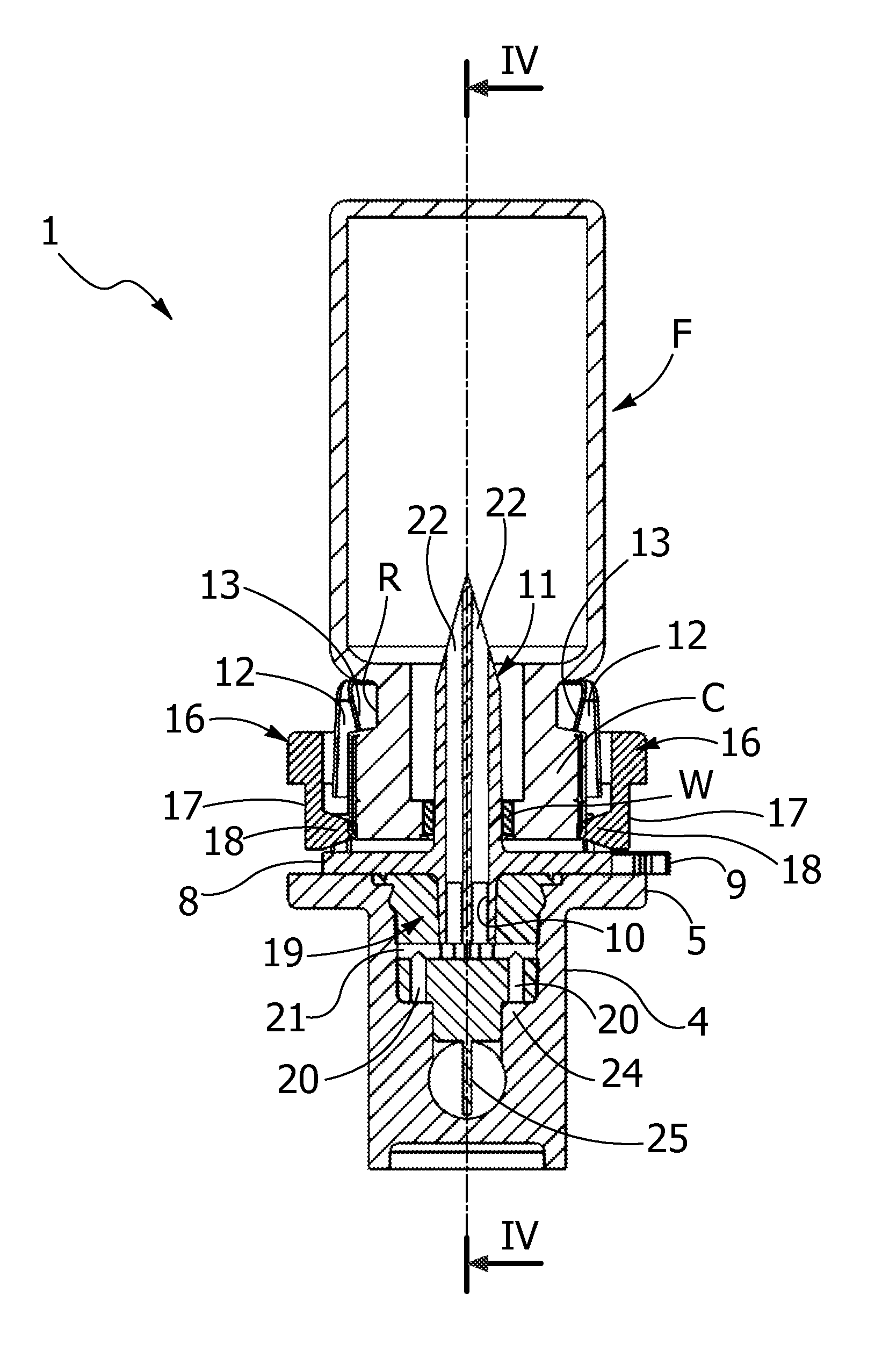
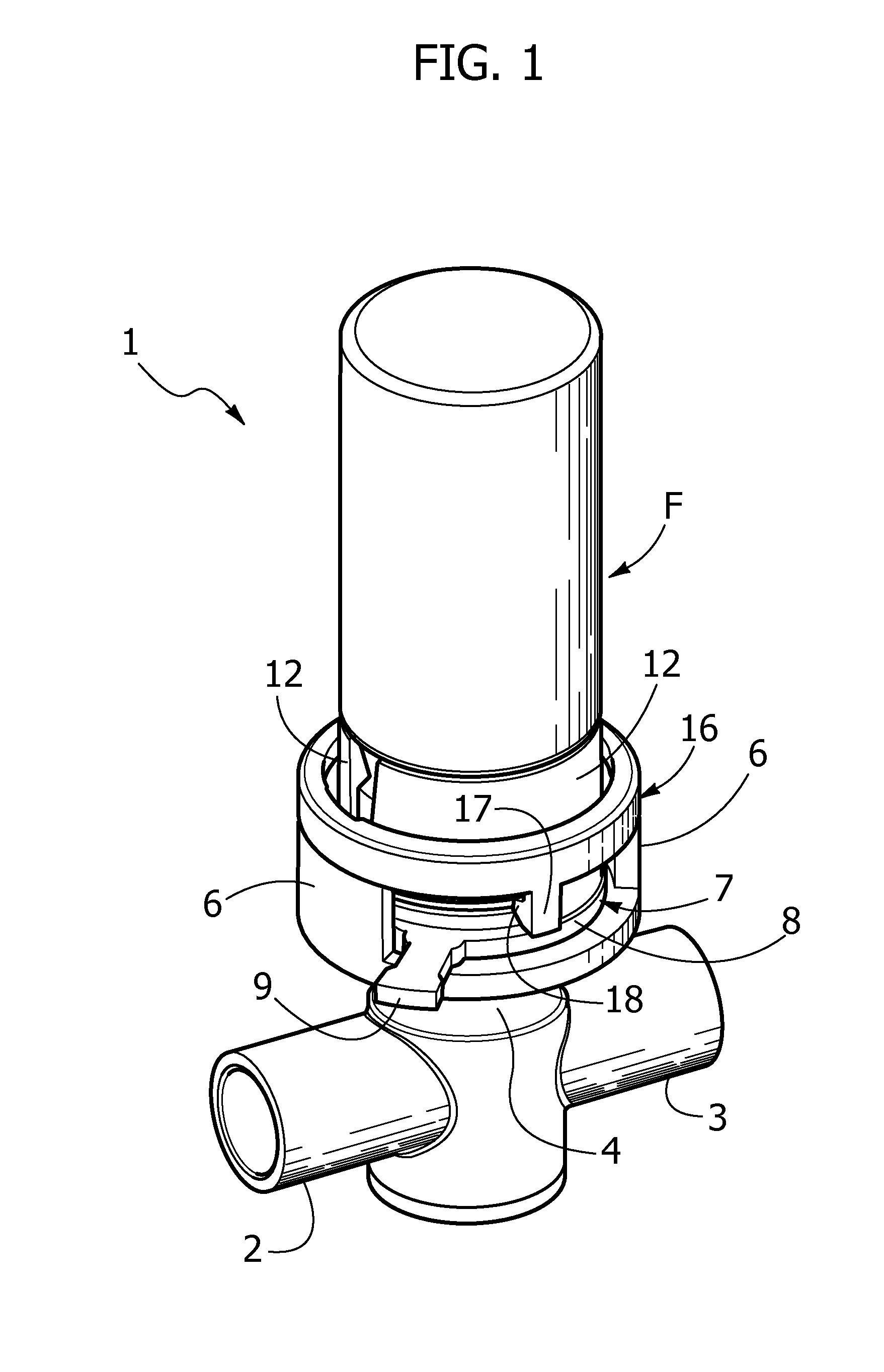
[0007]The object of the present invention is that of overcoming the abovementioned drawbacks, and provide a device for the controlled supply of a liquid into a medical flow line of the previously described type which does not require using syringes and allows introducing the secondary liquid into the flow line of the primary liquid, in an easily controllable manner, directly from the bottle or the like without requiring preliminary extraction of the secondary liquid from the relative bottle.
[0013]Due to this solution idea, the controlled supply of the liquid contained within the bottle or the like may be activated in a simple and safe manner directly therefrom, without requiring syringes and even by non-highly-skilled personnel.

Problems solved by technology

An alternative to the normal syringes is constituted by syringes or more generally by needleless supply devices which, though suitable to guarantee easier supply of the secondary liquid, are relatively more expensive and require a preliminary step of drawing the secondary liquid from the relative bottle.

Method used


Image

  • Device for the controlled supply of a liquid to a medical flow line
  • Device for the controlled supply of a liquid to a medical flow line
  • Device for the controlled supply of a liquid to a medical flow line

Examples


Embodiment Construction

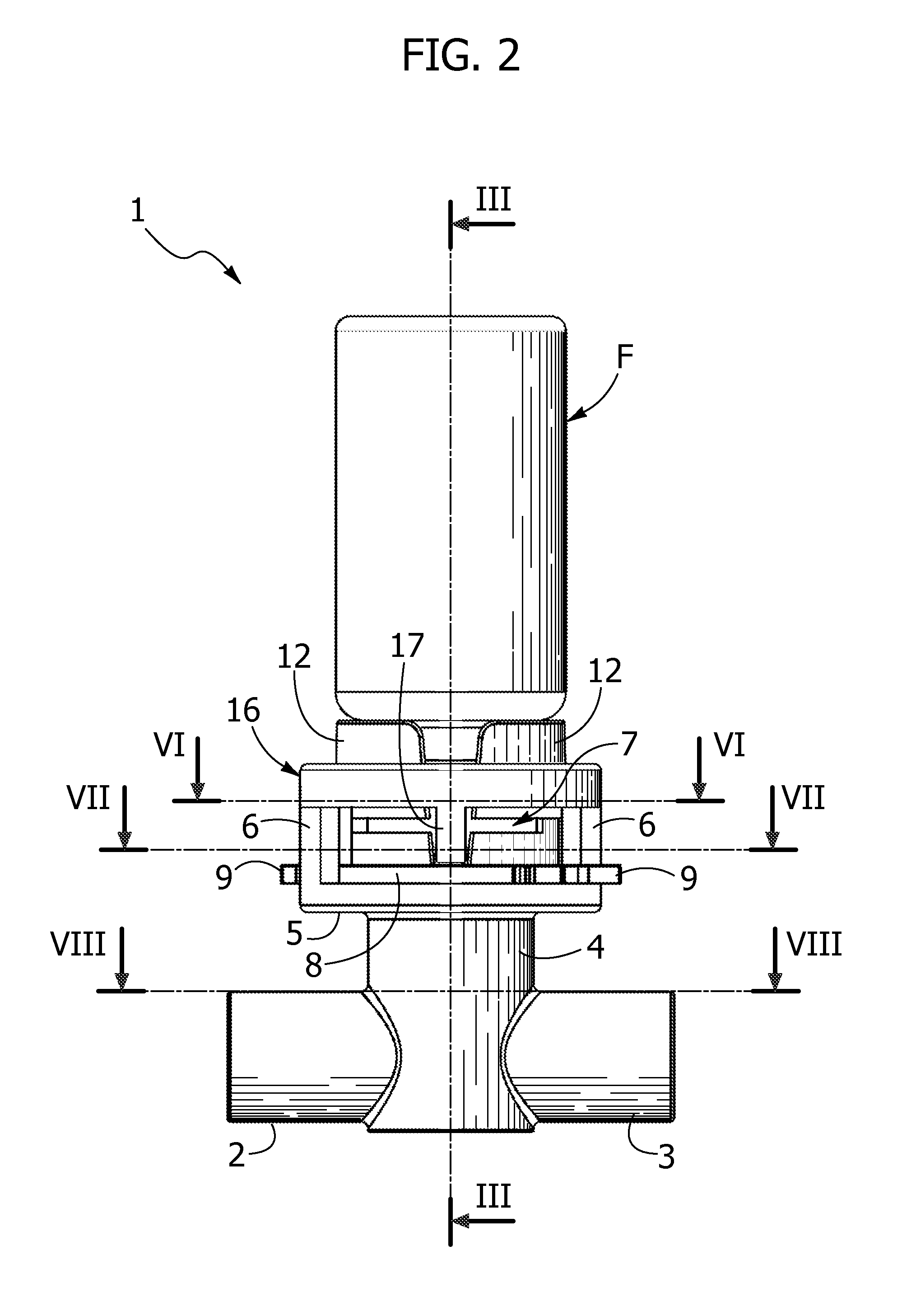
[0026]Initially referring to FIGS. 1 and 2 a device according to the invention for the controlled supply of a liquid, contained within a bottle or vial F, ad a medical flow line (for example for haemodialysis) including a tubular inlet connector 2 and a tubular outlet connector 3 intended to be connected conventionally to respective ducts, is indicated in its entirety with reference 1.

[0027]Referring to FIG. 5, the bottle F is typically made of glass and comprises a neck C with an annular groove R and a pierceable end wall W, typically including a diaphragm made of elastomeric material or the like.

[0028]The supply device 1 is arranged at an intermediate tubular connector 4, arranged between the inlet and outlet connectors 2, 3 transverse thereto, by means of which an annular base 5, having a pair of lateral edges 6 juxtaposed and spaced therebetween, is formed.

[0029]A hollow retaining body mounted rotatable, through methods clarified hereinafter, on the annular base 5 is indicated i...


PUM


Abstract

A device for the controlled supply of a liquid within a medical flow line, includes a retaining body rotatable on an intermediate tubular connector arranged between a tubular inlet connector and a tubular outlet connector of a primary liquid and within which a bottle pierceable and containing a secondary liquid can be fitted. The retaining body includes a hollow piercing spike, rotation blocking means of the retaining body disengageable following insertion of the bottle, axial stop means of the inserted bottle, and progressive opening means of a flow passage from the hollow spike to a flow line of the primary liquid during the rotation of the retaining body with the bottle inserted therein from a first angular position of complete closure to a second angular position of complete opening.

Description

CROSS REFERENCE TO RELATED APPLICATIONS[0001]This application is a national stage of PCT International Application No. PCT / IB2010 / 052583 filed on Jun. 10, 2010, and published in English on Dec. 23, 2010 as WO 2010 / 146506, which claims priority to Italian patent application number TO2009A000455 filed on Jun. 15, 2009, the entire disclosures of which are incorporated herein by reference.FIELD OF THE INVENTION[0002]The present invention generally refers to medical flow lines, particularly but not exclusively haemodialysis lines.[0003]In particular the invention refers to medical flow lines including a tubular inlet connector and a tubular outlet connector defining a flow line of a primary liquid and an intermediate tubular transverse connector arranged therebetween for the introduction of a secondary liquid into la flow line.PRIOR ART[0004]Typically, simple syringes, whose needle is capable of piercing an elastic diaphragm sealingly secured to the intermediate connector are used for th...

Claims


Application Information

Patent Timeline
Patent Type & Authority Patents(United States)
IPC IPC(8): E03D9/03
CPCA61M5/1409A61M5/162A61M2039/0205A61M39/223Y10T137/3112Y10T137/8766
Inventor GUALA, GIANNI
Owner IND BORLA
Learn More