
Camera mounted at rear of vehicle

a rear license plate and camera technology, applied in the field of rear license plate camera mounting system or vehicle back up aid, can solve the problems of not reaching widespread commercialization, the image device cannot be centrally located at the recess or well of the rear license plate, and the device is typically costly and complicated

Active Publication Date: 2014-04-15
MAGNA ELECTRONICS INC
View PDF61 Cites 33 Cited by
  • Summary
  • Abstract
  • Description
  • Claims
  • Application Information

AI Technical Summary

Benefits of technology

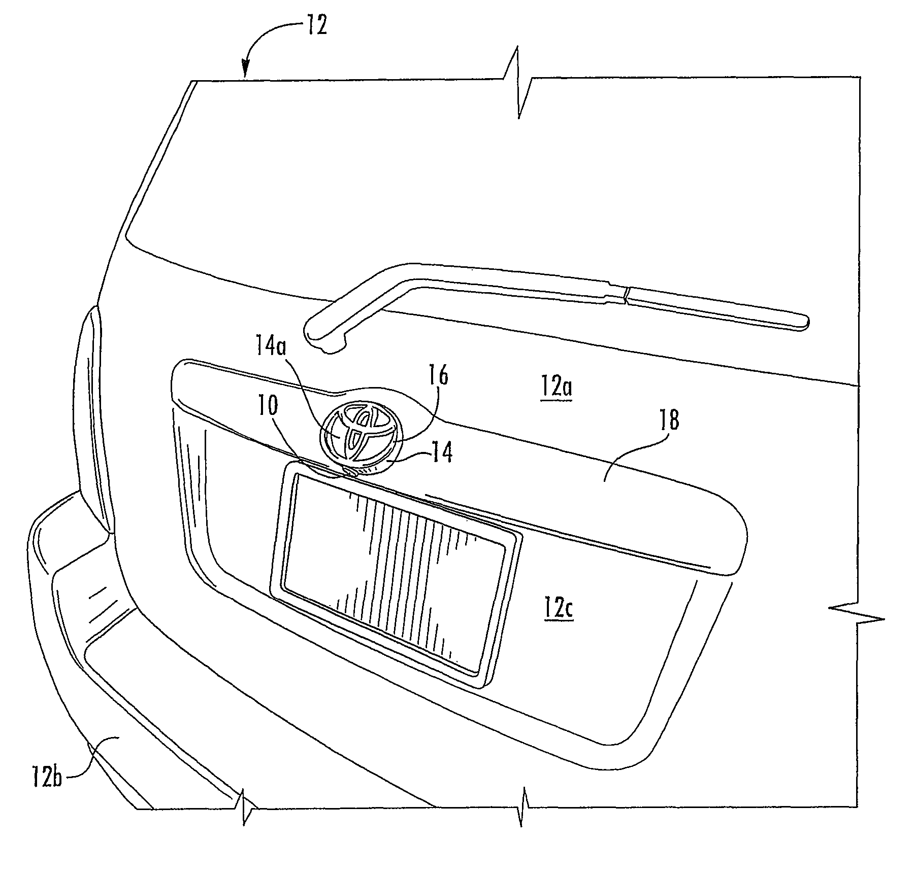
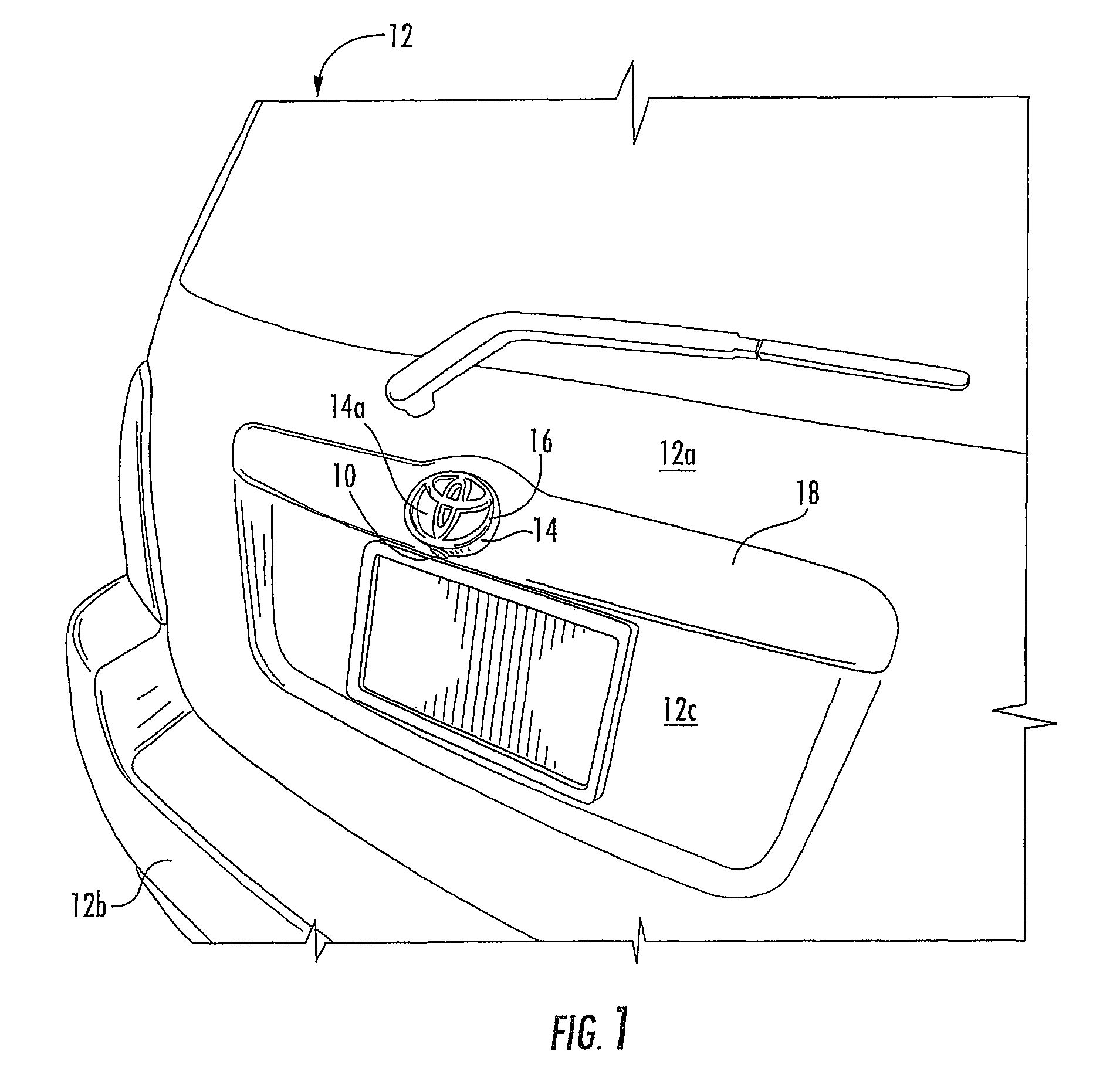
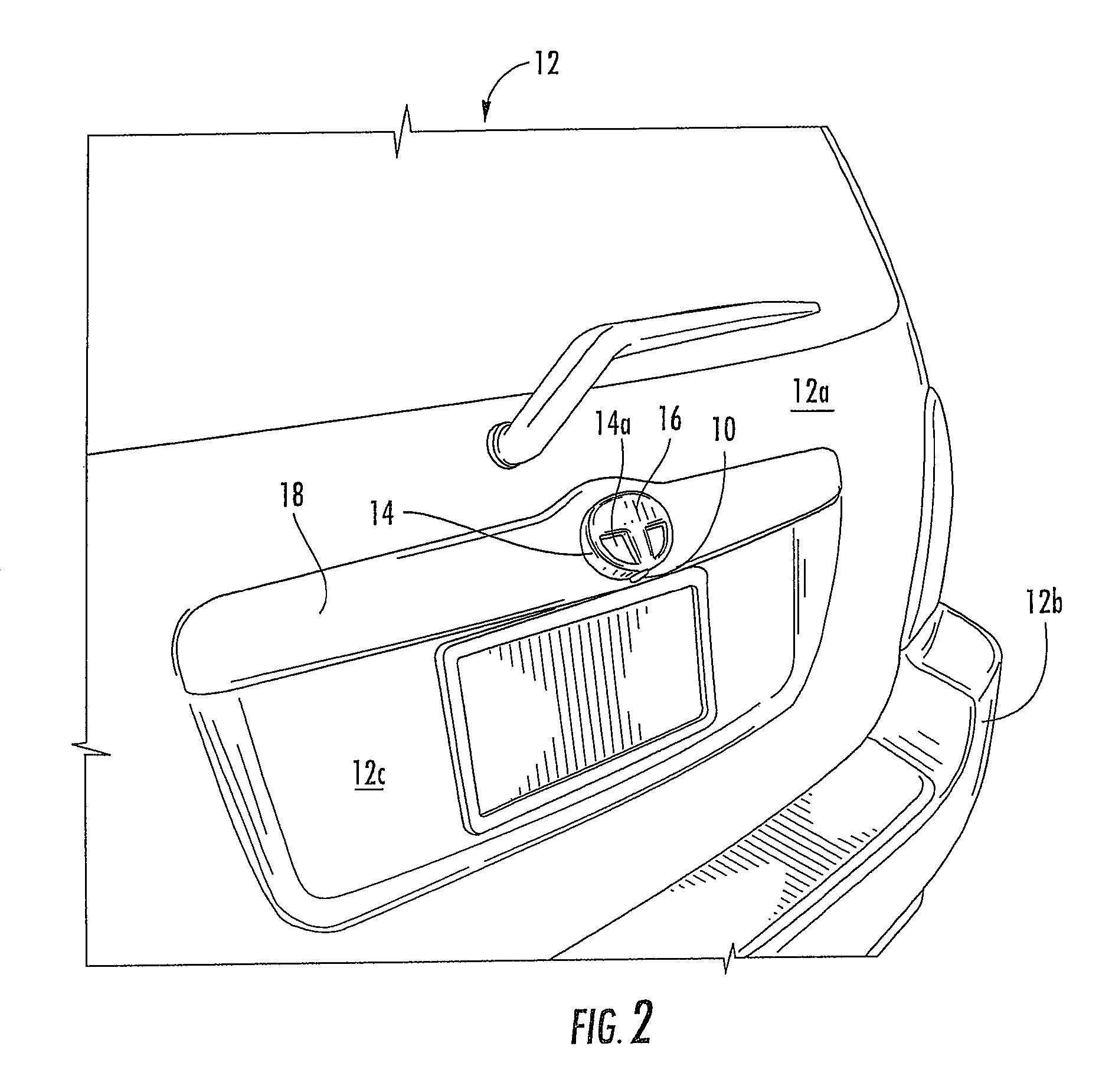
[0014]Therefore, the present invention provides an imaging device for a vehicle that may be positionable at a generally central location of a rear portion of a vehicle, and that may provide a generally downward and rearward field of view at the rear of the vehicle. The imaging device is proud of or positioned outward from a rear portion of the vehicle so that the downward field of view encompasses a portion of the rear of the vehicle, such as a vehicle bumper or the like. The imaging device may be fixedly positioned at the body surface or rear of the vehicle and thus the imaging system does not include costly and complex mechanical devices for extending and retracting the imaging device. The imaging device is positioned within an extender element that is substantially hidden or not readily noticeable or discernible by a person viewing the rear of the vehicle, so that the present invention provides a substantially concealed imaging device at a central region of the rear of the vehicle. A vehicle element, such as a functional element or a styling element, such as an exterior trim element or emblem or the like, is disposed at or attached to an outer surface of the extender element to substantially conceal or render covert the extender element and imaging device.

Problems solved by technology

However, it is desirable that such rearward and substantially downward facing imaging devices be generally centrally located at the rear of the vehicle, and many vehicles have a trunk or lift gate release handle at the central region of the sill or overhang portion, such that an imaging device cannot be centrally located at the recess or well of the rear license plate.
Such devices are typically costly and complicated devices and have not yet achieved widespread commercialization.

Method used


Image

  • Camera mounted at rear of vehicle
  • Camera mounted at rear of vehicle
  • Camera mounted at rear of vehicle

Examples


Embodiment Construction

[0023]Referring now to the drawings and the illustrative embodiments depicted therein, an imaging device or imaging sensor or camera 10 is located at a rear portion 12a of a vehicle 12 and has a generally rearward and downward field of view (FIGS. 1-5). As shown in FIGS. 1-5, imaging device 10 is located within a housing or encasement or extender element or tube 14 that protrudes rearwardly from the rear portion of the vehicle and that has a vehicle element 16 thereon, such as a vehicle emblem or decal or indicia or the like, so that the imaging device is not readily noticeable or discernible at the rear of the vehicle. The imaging device 10 thus is disposed at a location that is proud of or rearward of the rear surface of the rear portion 12a (such as a tailgate or lift gate or deck lid or the like) of the vehicle 12, such that the imaging device 10 may be directed substantially downward to have a field of view that encompasses the area immediately rearward of the vehicle and that ...


PUM


Abstract

A vehicle vision system includes a vehicle having a body surface and a vehicle element generally at the body surface. The vehicle element has a normal distance dimension relative to the body surface of the vehicle. The vehicle vision system includes an imaging device having an exterior field of view generally exterior of the vehicle for capturing images of a region external of the vehicle. An extender element is at the body surface and extends outwardly therefrom, and the vehicle element is disposed at an outer surface of the extender element, whereby the extender element extends the normal distance dimension of the vehicle element for accommodating the imaging device. The imaging device is disposed at least partially within the extender element, whereby the presence of the imaging device in the extender element is at least partially masked or camouflaged by the extender element and the vehicle element.

Description

CROSS REFERENCE TO RELATED APPLICATION[0001]The present application claims benefit of U.S. provisional application Ser. No. 60 / 765,797, filed Feb. 7, 2006, which is hereby incorporated herein by reference in its entirety.FIELD OF THE INVENTION[0002]The present invention relates to imaging systems for vehicles and, more particularly, to rear vision systems or back up aids for vehicles.BACKGROUND OF THE INVENTION[0003]It is known to provide a rearward facing camera or imaging sensor or device at a rear of a vehicle and with a generally rearward and downward field of view to capture images of the area immediately rearward of the vehicle for a rear vision system or back up aid system or the like. Examples of such rear vision devices and systems are described in U.S. Pat. Nos. 7,005,974; 6,989,736; 6,757,109; 6,717,610; 6,396,397; 6,201,642; 6,353,392; 6,313,454; 5,550,677; 5,670,935; 5,796,094; 5,877,897; 6,097,023; and 6,498,620, and International Publication No. WO 2004 / 047421 A2, pub...

Claims


Application Information

Patent Timeline
Patent Type & Authority Patents(United States)
IPC IPC(8): H04N7/00
CPCB60R2300/10B60R2011/004B60R13/005B60R2300/802B60R11/04B60R1/00H04N5/374H04N25/76
Inventor BRIGGANCE, WILLIAM, G.
Owner MAGNA ELECTRONICS INC
Learn More