Series-connected fan frame module

a fan frame and fan technology, applied in the direction of liquid fuel engines, marine propulsion, vessels, etc., can solve the problems of poor engaging effect between and more inconvenience during assembly, and achieve the effect of improving structural intensity

Active Publication Date: 2014-04-01
SUNONWEALTH ELECTRIC MACHINE IND
View PDF19 Cites 4 Cited by
  • Summary
  • Abstract
  • Description
  • Claims
  • Application Information

AI Technical Summary

Benefits of technology

[0011]It is therefore the primary objective of this invention to provide a series-connected fan frame module having a plurality of frames, in which both the axial disengagement and relative radial rotation between the frames are prevented via an engaging assembly. Furthermore, the series-connected fan frame module further utilizes an anti-rotation assembly to further prevent the relative radial rotation between the frames for improved structural intensity.
[0012]It is another objective of this invention to provide a series-connected fan frame module having a plurality of frames, in which quick assembly of the series-connected fan frame module can be provided to prevent the axial disengagement and relative radial rotation between the frames.

Problems solved by technology

As a result, the relative radial rotation between the first fan unit 81 and the second fan unit 82 easily results, leading to a poor engaging effect between the first fan unit 81 and the second fan unit 82.
However, in contrast to engaging the first fan unit 81 and the second fan unit 82 together, screwing the first fan unit 81 and the second fan unit 82 together causes more inconvenience during assembly.
Furthermore, similar problems arise for other conventional series-connected fan frame modules disclosed in the Taiwanese Patents numbered I285707, M278954, M285198, M285199, M333037 and M343076, so they are not described herein again for brevity.

Method used


Image

  • Series-connected fan frame module
  • Series-connected fan frame module
  • Series-connected fan frame module

Examples


Embodiment Construction

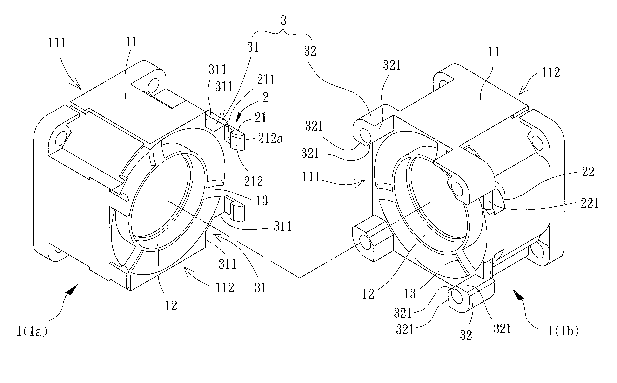
[0024]Referring to FIG. 4, a series-connected fan frame module including two frames 1, an engaging assembly 2 and an anti-rotation assembly 3 is disclosed according to a preferred embodiment of the invention. The frames 1 are coupled together in series. The engaging assembly 2 is arranged on both frames 1 to prevent the axial disengagement and relative radial rotation between the frames 1. The anti-rotation assembly 3 is also arranged on both frames 1 to further prevent the relative radial rotation between the frames 1.

[0025]The frames 1 may be of an axial-flow or centrifugal type, and each has a frame body 11. The frame body 11 is hollow and includes an air inlet 111 and an air outlet 112. The frame body 11 further includes a base 12 disposed therein for coupling components such as a motor or the like (the details are described later).

[0026]In the embodiment, the frames 1 are of the axial-flow type. The air inlet 111 and the air outlet 112 are axially aligned. The base 12 is dispos...


PUM


Abstract

A series-connected fan frame module includes a plurality of frames, an engaging assembly and an anti-rotation assembly. The frames are arranged in series. The engaging assembly is arranged on each of the frames to couple the frames in series. The anti-rotation assembly is arranged on each of the frames and includes at least one position-fixing member and at least one blocking member arranged on portions of adjacent two of the frames where the adjacent two of the frames are coupled together. The at least one position-fixing member is engaged with the at least one blocking member to prevent relative radial rotation between the adjacent two of the frames.

Description

BACKGROUND OF THE INVENTION[0001]1. Field of the Invention[0002]The present invention generally relates to a series-connected fan frame module and, more particularly, to a series-connected frame fan module that has a plurality of frames connected in series, in which axial disengagement and relative radial rotation of the frames are prevented.[0003]2. Description of the Related Art[0004]Referring to FIG. 1, Taiwanese Patent Number 569663 discloses a conventional series-connected fan frame module, which includes a first fan unit 81, a second fan unit 82 and two coupling members 83 and 84. The coupling members 83 and 84 couple the first fan unit 81 and the second fan unit 82 together in series. One of the coupling members 83 and 84 is in the form of engaging grooves while the other one is in the form of engaging tongues.[0005]In the conventional series-connected fan frame module 8, the first fan unit 81 and the second fan unit 82 are mainly connected in series via the coupling members ...

Claims


Application Information

Patent Timeline
Patent Type & Authority Patents(United States)
IPC IPC(8): F01D25/28
CPCF04D25/06F04D25/08F04D29/601
Inventor WU, ZHE-HAOCHANG, CHIH-MING
Owner SUNONWEALTH ELECTRIC MACHINE IND
Why Eureka
Try Eureka