Gas generator and airbag apparatus

a gas generator and airbag technology, applied in the direction of vehicles, pedestrian/occupant safety arrangements, weapons, etc., can solve the problems of airbag apparatus having gas generators that may rattle, complicated assembly operation, etc., to reduce the rattling of the assembled inflator, facilitate the assembly of the inflator, and increase the width of the inl

Active Publication Date: 2014-04-01
TOYODA GOSEI CO LTD
View PDF13 Cites 16 Cited by
  • Summary
  • Abstract
  • Description
  • Claims
  • Application Information

AI Technical Summary

Benefits of technology

[0010]Accordingly, it is an objective of the present invention to provide a gas generator and an airbag apparatus that facilitate assembly of an inflator to a retainer and reduce rattling of the assembled inflator.
[0011]To achieve the foregoing objective, and in accordance with one aspect of the present invention, a gas generator having an elongated inflator which discharges gas for inflation and a retainer having a holding portion is provided. The holding portion covers part of the inflator with respect to a direction of an axis of the inflator. A positioning protrusion for determining the position of the inflator relative to the retainer is formed on an outer surface of the inflator. The retainer includes an engagement base and a tongue piece. The tongue piece extends in the direction of the axis of the inflator and from a position separated from the engagement base in the circumferential direction of the holding portion. The engagement base has an engagement portion. The tongue piece has an engagement portion located at a position separated from a basal end of the tongue piece. The engagement portion of the engagement base and the engagement portion of the tongue piece face each other such that an engagement space is formed between the engagement portions, into which space the positioning protrusion enters. The engagement space has an inlet the width of which is less than a size of the positioning protrusion. In a state in which part of the inflator is covered with the holding portion, when the inflator is rotated or moved to cause the positioning protrusion of the inflator to increase the width of the inlet, the tongue piece is elastically deformed about a fulcrum, which is the basal end of the tongue piece, to increase the width of the inlet.

Problems solved by technology

These steps complicate the assembling operation.
Likewise, the airbag apparatus having the gas generator may rattle.

Method used


Image

  • Gas generator and airbag apparatus
  • Gas generator and airbag apparatus
  • Gas generator and airbag apparatus

Examples


first embodiment

[0040]A gas generator 10 and an airbag apparatus 60 according to a first embodiment will now be described with reference to FIGS. 1 to 13.

[0041]The airbag apparatus 60 is installed in a vehicle. The gas generator 10 forms part of the airbag apparatus.

[0042]FIG. 11 illustrates the airbag apparatus 60 having the gas generator 10. When an impact is applied to the vehicle due to, for example, a collision, the airbag apparatus 60 shown in FIG. 11 causes the gas generator 10 to generate inflation gas to deploy and inflate an airbag 50 at a position in the vicinity of an occupant seated in a vehicle seat, thereby protecting the occupant from the impact.

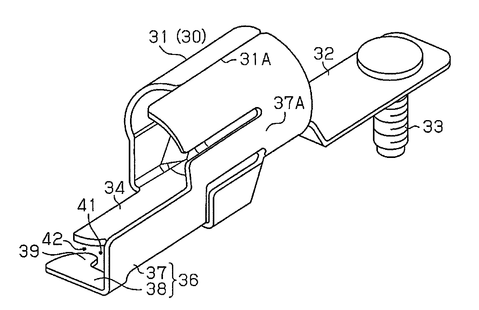
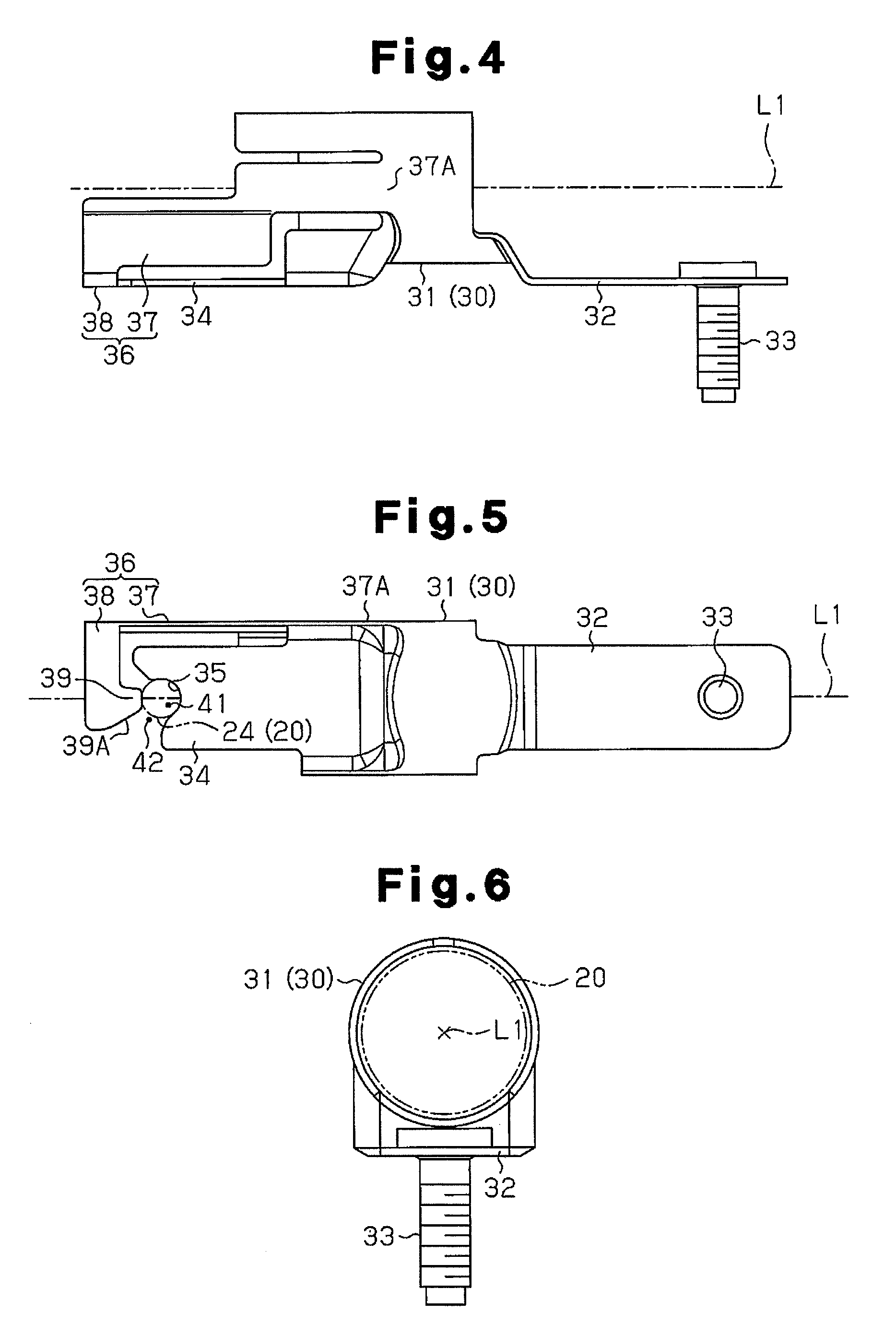
[0043]The gas generator 10 includes a retainer 30, which is secured to the airbag 50, and an inflator 20, which is assembled with the retainer 30 and discharges inflation gas.

[0044]Components of gas generator 10 will now be described.

20>

[0045]As shown in FIGS. 8 and 9, the inflator 20 has an elongated columnar shape and accommodates in it a ...

second embodiment

[0114]A gas generator and an airbag apparatus according to a second embodiment will now be described with reference to FIGS. 14 to 17B.

[0115]The second embodiment is different from the first embodiment in the structure of the engagement base 34 and a tongue piece in the retainer 30. The differences between the second embodiment and the first embodiment will be mainly discussed.

[0116]An inflator 20 is configured to be movable (in a straightly line) in the direction of the axis L1 with part of the inflator 20 covered with a holding portion 31.

[0117]As shown in FIGS. 14 and 15, the holding portion 31 of the retainer 30 has a single engagement base 34 and a pair of tongue pieces (first and second tongue pieces) 71, 75, which extend in the direction of the axis L1 and away from the attaching protrusion 33. The first tongue piece 71 and the second tongue piece 75 are located on opposite sides of the engagement base 34 in the circumferential direction of the holding portion 31. In other wo...

third embodiment

[0152]A gas generator and an airbag apparatus according to a third embodiment will now be described with reference to FIGS. 18 to 20B.

[0153]The third embodiment is different from the second embodiment in the structure of the first engagement portion 35 and the second engagement portions 74, 78 in the retainer 30.

[0154]In place of the second inclined portions 74B, 78B of the second embodiment, the second engagement portions 74, 78 of the third embodiment have parallel portions 74C, 78C. When the attaching protrusion 24 is clamped by the first engagement portion 35 and the second engagement portions 74, 78, that is, when none of the first and second tongue pieces 71, 75 (none of the elastic portions 72, 76) is elastically deformed, the parallel portions 74C, 78C are parallel with the axis L1. Since the parallel portions 74C, 78C are formed on the second engagement portions 74, 78, the second engagement portions 74, 78 have corners 74D, 78D at positions that are close to the engagement...


PUM


Abstract

A gas generator includes an inflator and a retainer. The retainer includes a holding portion, which partially covers the inflator. The inflator has an attaching protrusion for determining the position relative to the retainer. The retainer includes an engagement base and a tongue piece. The tongue piece extends in an axial direction of the inflator and from a position separated from the engagement base in the circumferential direction of the holding portion. The engagement base and the tongue piece each have an engagement portion. The engagement portions face each other to form an engagement space therebetween, into which the attaching protrusion enters. The engagement space has an inlet the width of which is less than the size of the positioning protrusion. When the inflator causes the positioning protrusion to increase the width of the inlet, the tongue piece is elastically deformed about a basal end of the tongue piece.

Description

BACKGROUND OF THE INVENTION[0001]The present invention relates to a device for generating gas and an airbag apparatus for protecting an occupant from an impact by inflating an airbag with gas generated by the gas generator.[0002]An airbag apparatus protects an occupant from an impact when an impact due to, for example, a collision is applied to a vehicle. The airbag apparatus causes a gas generator to generate gas in response to an impact, and uses the gas to inflate an airbag in the vicinity of the occupant to reduce the impact applied to the occupant.[0003]Known gas generators include a columnar inflator for generating gas and a retainer that covers the inflator and fastens the inflator to a component of a vehicle.[0004]For example, Japanese Laid-Open Patent Publication No. 2011-121469 discloses an airbag apparatus that includes an inflator having bolts on the outer surface. The bolts are separated from each other in the axial direction of the inflator. The bolts protrude in a dir...

Claims


Application Information

Patent Timeline
Patent Type & Authority Patents(United States)
IPC IPC(8): B60R21/16
CPCB60R21/2171C06D5/00B60R21/263
Inventor HONDA, KENSAKUSATO, YUJIIIDA, TAKASHIGOTO, YOSHIAKIHOTTA, MASASHISATO, EIJIYAMASHITA, AKIRAHISHIKI, YOSHIHIKOTAKEI, YOSHINARIIZOE, KIKUYONIMI, NAOKIHOSOI, TOSHIHIRO
Owner TOYODA GOSEI CO LTD
Why Eureka
Try Eureka