
Gift storage device of gift game machine and selection output means thereof

a technology of gift game machines and storage devices, which is applied in the direction of instruments, sport equipment, and apparatus for dispensing discrete objects, can solve the problems of interference between the arrangement of the motors, and achieve the reduction of the cost of the gift game machine, and the amount of electricity consumed by the whole machine. , the effect of facilitating the disassembly of the gift storage devices

Inactive Publication Date: 2014-03-25
YOUAL JIFH ENTERPRISE
View PDF8 Cites 1 Cited by
  • Summary
  • Abstract
  • Description
  • Claims
  • Application Information

AI Technical Summary

Benefits of technology

[0006]The objective of the present invention is to solve the problem in prior art that the motors are arranged to correspond to the gift storage devices respectively in the conventional gift game machine. The solution of the present invention is to employ a selection output means which is movable along X, Y, Z axes to control a plurality of gift storage devices. In this way, the number of the motors, the cost of the gift game machine, and the amount of electricity consumed by the whole machine are reduced. Further, the control and maintenance of the whole gift game machine becomes less complicated. On the other hand, in the present invention, one motor is arranged to control the operations of a plurality of gift storage devices. Thus, the problem in prior art that the disassembly of the gift storage devices may be interfered with the arrangement of the motors is solved. Since the structure of the present invention facilitates the disassembly of the gift storage devices, the number and locations of the gift storage devices on a back plate of the gift game machine can be adjusted free and easily based on the standards (such as number, dimension, weight, pitch) of the gifts.

Problems solved by technology

Thus, the problem in prior art that the disassembly of the gift storage devices may be interfered with the arrangement of the motors is solved.

Method used


Image

  • Gift storage device of gift game machine and selection output means thereof
  • Gift storage device of gift game machine and selection output means thereof
  • Gift storage device of gift game machine and selection output means thereof

Examples


Embodiment Construction

[0025]As shown in FIG. 7, the present invention provides a gift game machine, which includes a plurality of detachable gift storage devices 10 and a selection output means 50.

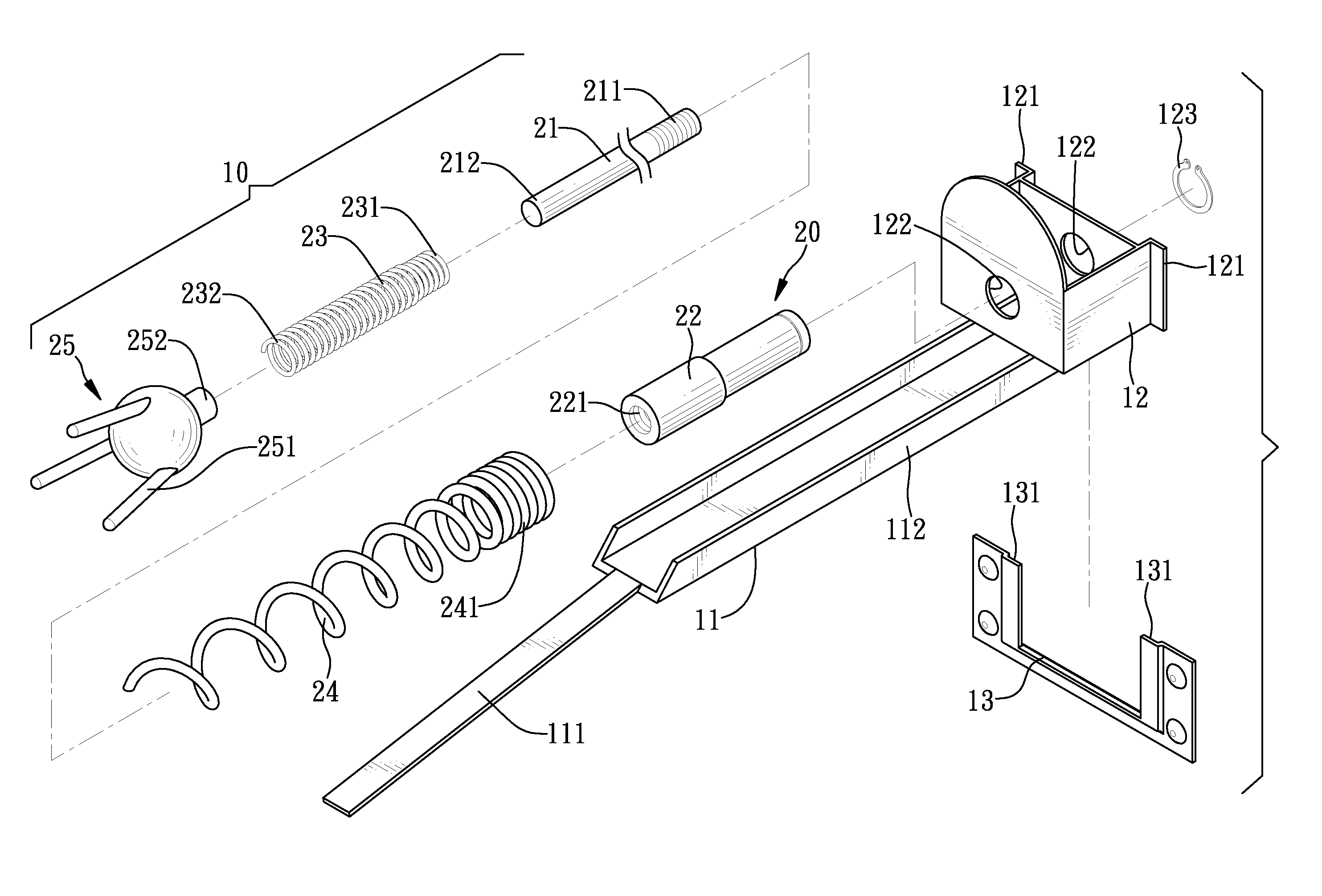
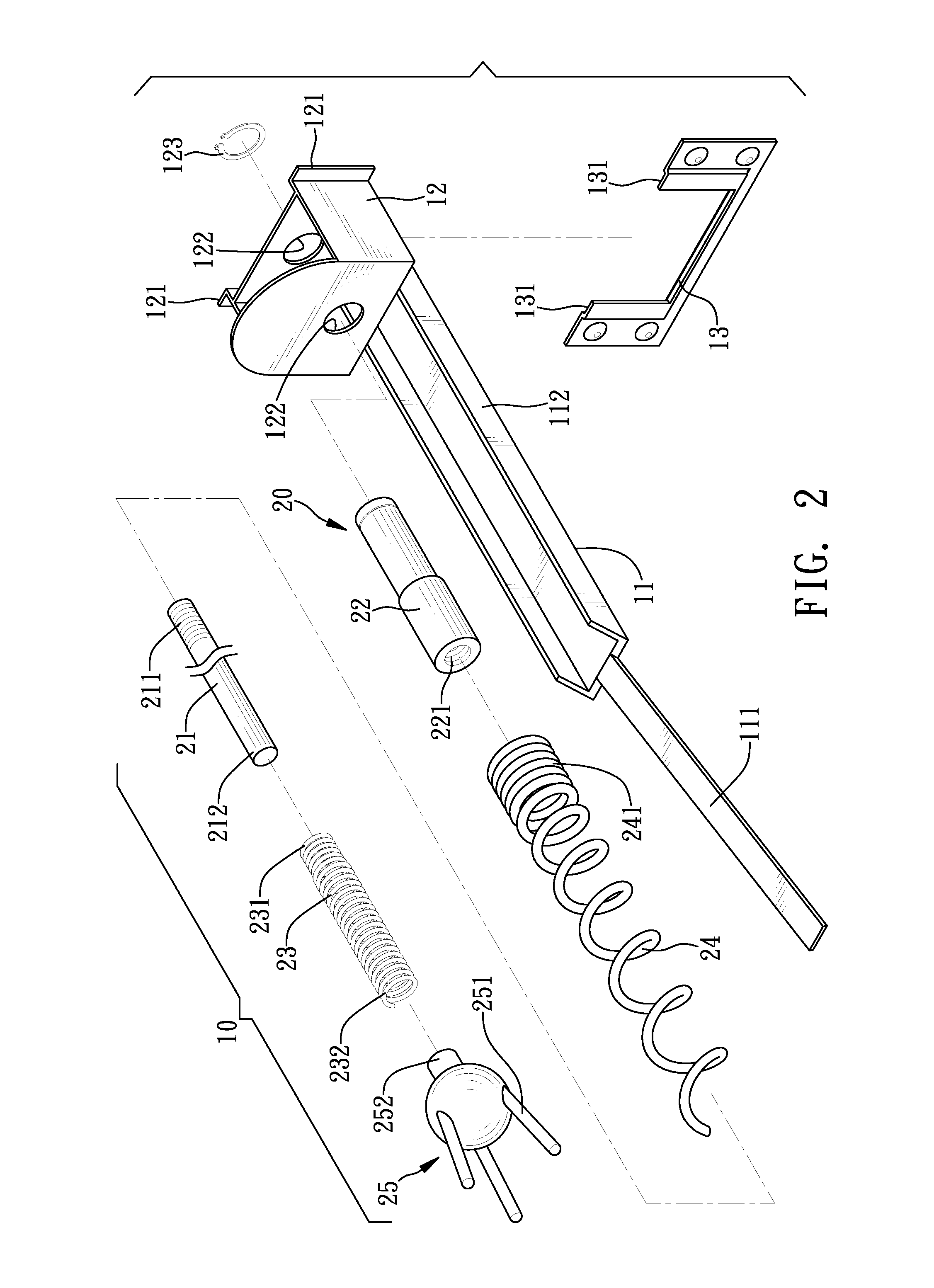
[0026]As shown in FIGS. 2 to 4, the detachable gift storage device 10 includes a gift support 11, a base 12, an insertion frame 13, and a rotary feeding set 20.

[0027]The gift support 11 has a U-shaped cross section and extends in a certain length. A first end 111 of the gift support 11 is inclined downwardly to form an exhaust plate. A second end 112 of the gift support 11 is combined with the base 12. An insertion frame 13 is fixed to a back plate 90 of the gift game machine by screws. Tabs 121 and insertion troughs 131 are formed between the base 12 and the insertion frame 13. The insertion troughs 131 are formed as top openings of the insertion frame 13, whereby each tab 121 can disassembly enter a corresponding one of the insertion trough 131 for mounting the base 12. A plurality of gifts 100 are hung on th...


PUM


Abstract

The present invention provides a gift storage device of a gift game machine and a selection output means thereof. The gift game machine has the selection output means movable in X, Y, Z axes to correspond to a plurality of gift storage devices. Each gift storage device includes a gift support for allowing gifts to hang thereon and a rotary feeding set controlled by the selection output means. A spiral element of the rotary feeding set rotates to push the gifts on the gift support, so that the gifts can move on the gift support until they leave the gift support. Each gift storage device is positioned to a back plate of the gift game machine via an insertion frame. Tabs and insertion troughs are provided between the gift storage device and the insertion frame, so that the gift storage device can be disassembled or assembled easily.

Description

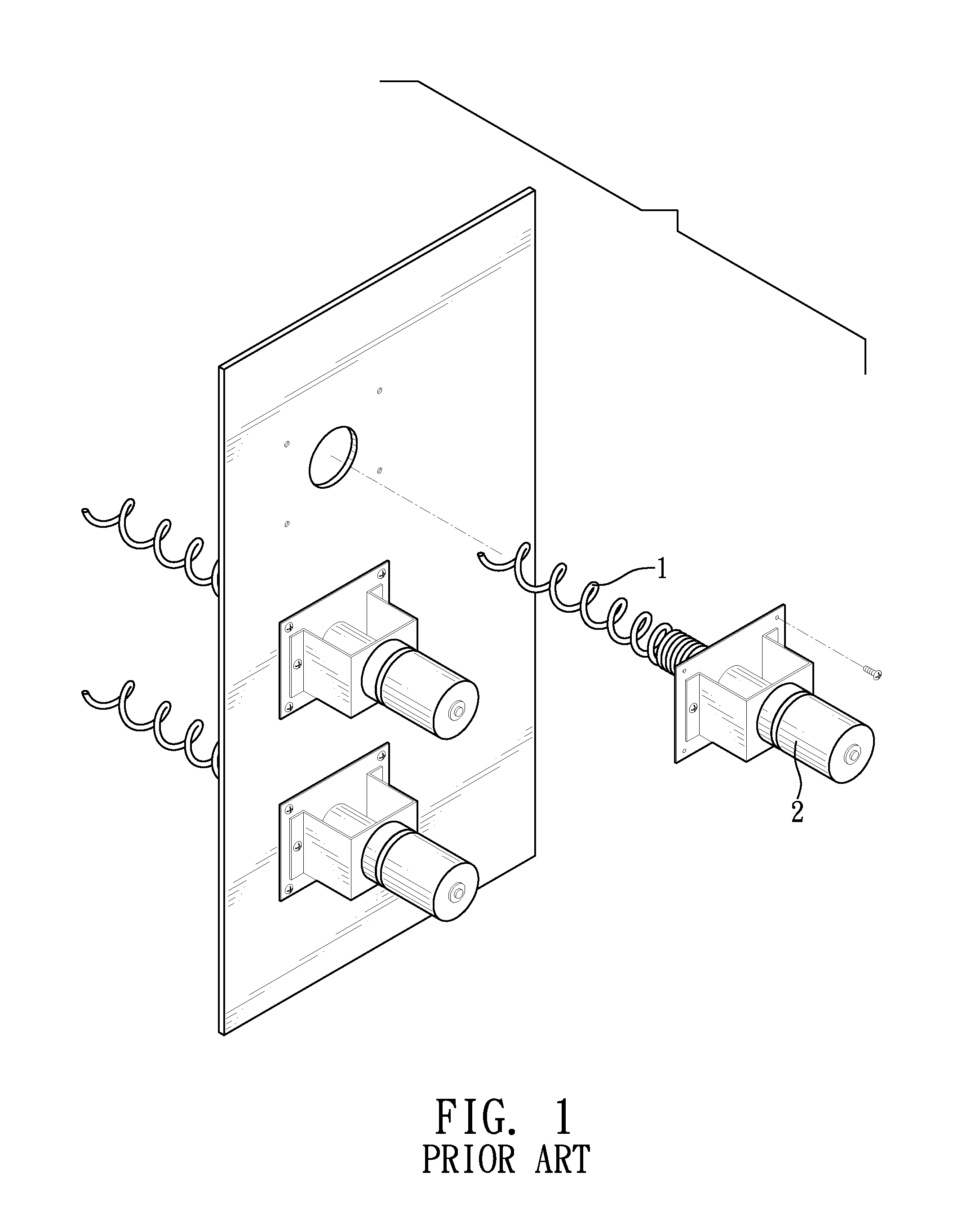
BACKGROUND OF THE INVENTION[0001]1. Field of the Invention[0002]The present invention relates to a gift game machine having a plurality of axially rotatable gift storage devices. The gifts are sequentially hung on the gift storage devices. The gift storage devices are controlled by a selection output means to output the selected gift.[0003]2. Description of Prior Art[0004]FIG. 1 shows a conventional gift game machine having a plurality of spiral gift storage devices 1. Gifts are sequentially hung on each gift storage device 1. Motors 2 are arranged to correspond to the gift storage devices 1 respectively. A player chooses a desired gift and then activates the motor 2 of the gift storage device 1 containing the selected gift, whereby the gift storage device 1 of interest can axially rotate to output the gifts contained therein until the foremost gift leaves the gift storage device 1.[0005]The above-mentioned gift game machine has the following problems: the motors 2 are arranged to c...

Claims


Application Information

Patent Timeline
Patent Type & Authority Patents(United States)
IPC IPC(8): A63F7/36
CPCG07F17/3297G07F11/64G07F11/42
Inventor WANG, CHIH-CHIEH
Owner YOUAL JIFH ENTERPRISE
Learn More