
Wearable RFID system

a technology of rfid system and wearable body, which is applied in the field of wearable rfid system, can solve the problems of limited rfid portal, data collection still needs to be confirmed, and the aim of rfid device erodes at least some benefits, so as to facilitate the reading of the tag, increase the read range, and increase the read accuracy

Active Publication Date: 2014-03-18
METRC LLC
View PDF19 Cites 53 Cited by
  • Summary
  • Abstract
  • Description
  • Claims
  • Application Information

AI Technical Summary

Benefits of technology

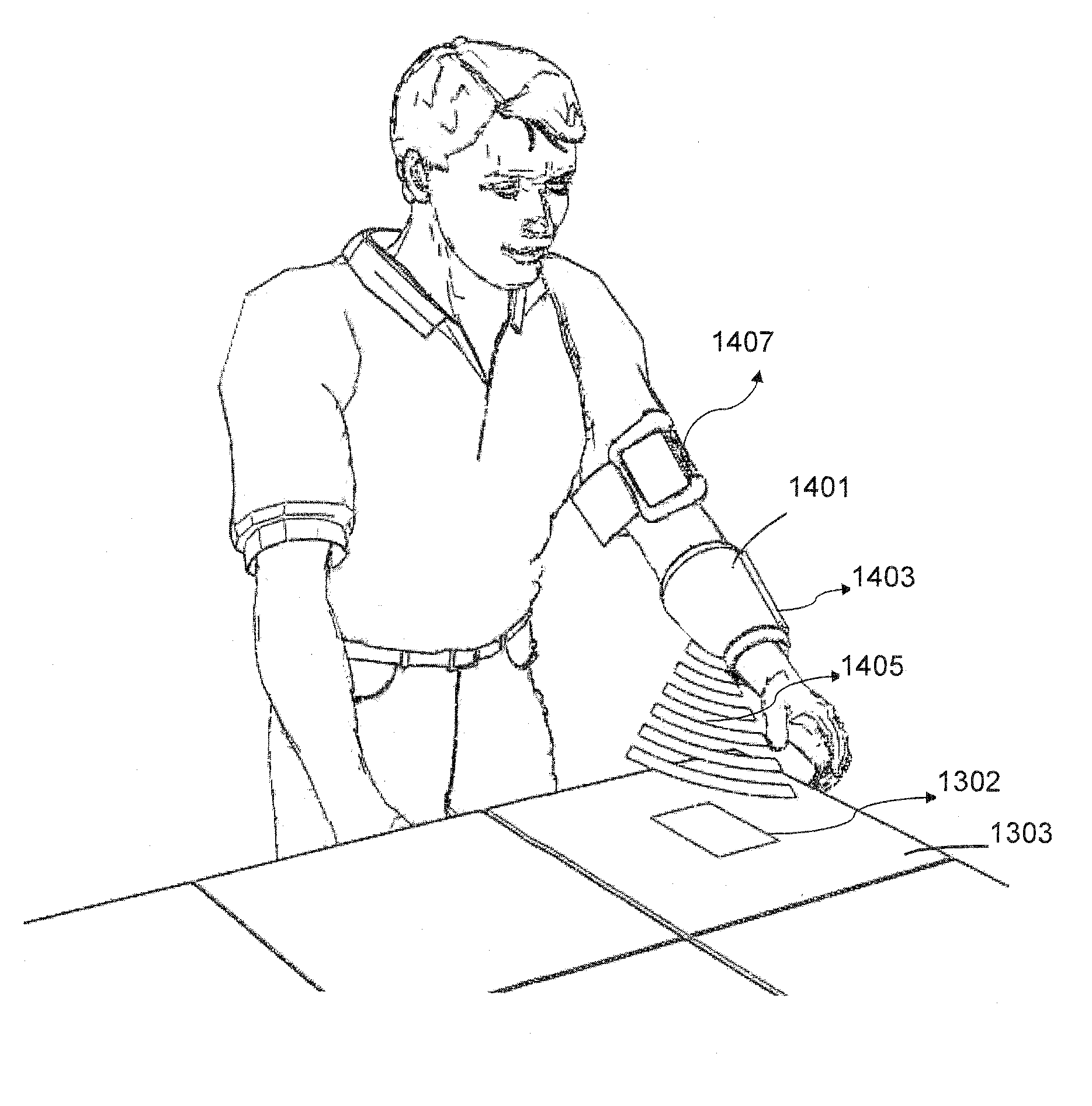
[0008]Embodiments of the subject invention offer significant improvement over prior wearable RFID systems in that they do not require that the RF antenna be pointed directly at each item's tag as items are processed. Instead, according to embodiments of the subject invention an RF antenna is positioned so that during normal handling of tagged items the antenna is generally oriented toward the handled item. An increased read range and other enhancements facilitate the reading of the tag without “aiming” or other extraneous motion by the worker. In embodiments of the subject invention, the system is further enhanced by the addition of sensors that indicate when interrogation should be initiated for a particular item or group of items, thus increasing read accuracy and saving battery life. In further embodiments, the RFID system incorporates other identification apparatus, such as a barcode scanner, to corroborate the radio frequency identification of handled items.

Problems solved by technology

RFID systems often have reading or interrogation fields having a wide range which can present a problem of differentiating an individual product or a case that needs to be detected among other tagged items.
RFID portals are limited in that they distinguish only the items passing through the portal, for example, a duck door, while reading every other tag in the field.
Having to aim the RFID device undermines at least some of the benefits of using an RFID system.
Moreover, the data collected still needs to be confirmed due to the high probability of reading an unwanted tag.
These aimed devices can also occupy the user's hands, making handling of items more difficult or time consuming.
Current wearable RFID systems have antenna designs that severely limit their interrogation or read ranges.
This aiming can disrupt a worker's normal handling of tagged objects and decrease processing accuracy or efficiency.
Initial studies show that aiming can significantly increase the processing time required when handling items.

Method used


Image

  • Wearable RFID system
  • Wearable RFID system
  • Wearable RFID system

Examples


Embodiment Construction

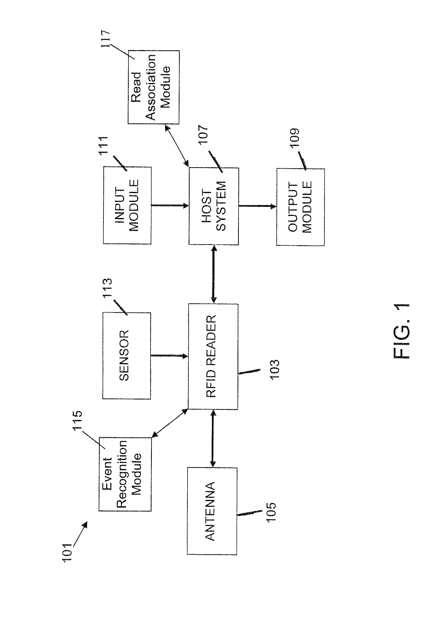
[0027]Embodiments of the present invention include improved systems and methods for radio frequency identification (RFID) using a wearable RFID antenna. In one embodiment of the subject invention, a wearable RFID system is provided, including an antenna, an RFID reader, a host system, and a holder for holding at least the antenna and the reader. In specific embodiments, the wearable RFID system also incorporates a transmitting antenna or interrogator in the holder, for production of an interrogation RF signal that creates a response RF signal upon incidence on a RFID tag or transponder. The RFID reader or host system can drive the transmitting antenna or a separate transmitter can be provided. In a specific embodiment, one antenna acts as both the transmitting antenna and the receiving antenna. In alternative embodiments, the transmitting antenna can be separate from the holder, and / or not attached to the wearer of the holder. Similarly, the host system can be located on the holder,...


PUM


Abstract

Apparatus and methods are provided for automatically interrogating a tagged object using radio frequency identification (RFID) when the object is moved. In one embodiment, a worker is outfitted with a wearable RFID system including an RF antenna, an RFID reader, and a holder to hold the antenna and reader during operation. The system is worn by the worker while the worker moves objects from one place to another. When the worker moves an object with an attached RFID tag, the antenna automatically begins scanning for signals from the object's RFID tag. When a RF signal is received by the antenna, the RFID reader collects the signal and transmits it to a host system which processes the signal to obtain information related to the object to which the RFID tag is attached.

Description

CROSS-REFERENCE TO RELATED APPLICATION[0001]The present application claims the benefit of U.S. Provisional Application Ser. No. 61 / 171,516, filed Apr. 22, 2009 and U.S. Provisional Application Ser. No. 61 / 324,044, filed Apr. 14, 2010, both of which are hereby incorporated by reference herein in their entirety, including any figures, tables, or drawings.BACKGROUND OF INVENTION[0002]Radio frequency identification (RFID) technology enables automatic identification of unique items by using radio frequency (RF) signals. A typical RFID system includes a tag, a reader, an antenna, and a host system. The reader gathers information about an object by communicating through the antenna with the tag attached to the object. The host system then processes the data collected by the reader to obtain information related to the tagged object.[0003]RFID systems often have reading or interrogation fields having a wide range which can present a problem of differentiating an individual product or a case ...

Claims


Application Information

Patent Timeline
Patent Type & Authority Patents(United States)
IPC IPC(8): H04Q5/22
CPCG06K7/10396G06K7/10079G06K7/10128G06K7/0008G06K7/10009
Inventor UYSAL, DILEK DAGDELENALTUNBAS, AHMET ERDEMWELLS, JEFFREY LANE
Owner METRC LLC
Learn More